Combustor
A combustor is a component or area of a gas turbine, ramjet, or scramjet engine where combustion takes place.
In a gas turbine engine, the combustor or combustion chamber is fed high-pressure air by the compression system.
Today three main configurations exist: can, annular, and cannular (also referred to as can-annular tubo-annular).
As with any engineering challenge, accomplishing this requires balancing many design considerations, such as the following: Sources:[1][2] Advancements in combustor technology focused on several distinct areas; emissions, operating range, and durability.
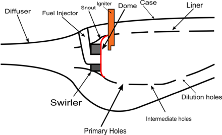
[5] The purpose of the diffuser is to slow the high-speed, highly compressed, air from the compressor to a velocity optimal for the combustor.
The two primary differences are in the resulting temperature profile of the liner and the amount of cooling air required.
[8] Early combustors tended to use bluff body domes (rather than swirlers), which used a simple plate to create wake turbulence to mix the fuel and air.
The swirler establishes a local low pressure zone that forces some of the combustion products to recirculate, creating the high turbulence.
It is highly compressed air from the high-pressure compressor (often decelerated via the diffuser) that is fed through the main channels in the dome of the combustor and the first set of liner holes.
This air completes the reaction processes, diluting the high concentrations of carbon monoxide (CO) and hydrogen (H2),[20] and also helps cooling down the gases from combustion.
[22] The primary air from the compressor is guided into each individual can, where it is decelerated, mixed with fuel, and then ignited.
The secondary air also comes from the compressor, where it is fed outside of the liner (inside of which is where the combustion is taking place).
[23] In most applications, multiple cans are arranged around the central axis of the engine, and their shared exhaust is fed to the turbine(s).
Can-type combustors are easy to maintain, as only a single can needs to be removed, rather than the whole combustion section.
Most modern gas turbine engines (particularly for aircraft applications) do not use can combustors, as they often weigh more than alternatives.
Unlike the can combustor, all the combustion zones share a common ring (annulus) casing.
[29] The combustion zones can also "communicate" with each other via liner holes or connecting tubes that allow some air to flow circumferentially.
The exit flow from the can-annular combustor generally has a more uniform temperature profile, which is better for the turbine section.
[30] Examples of gas turbine engines utilizing a can-annular combustor include the General Electric J79 turbojet and the Pratt & Whitney TF30 and Rolls-Royce Tay turbofans.
Annular combustors do away with the separate combustion zones and simply have a continuous liner and casing in a ring (the annulus).
There are many advantages to annular combustors, including more uniform combustion, shorter size (therefore lighter), and less surface area.
At high power levels, the main zone is used as well, increasing air and mass flow through the combustor.
[38] Carbon dioxide is a product of the combustion process, and it is primarily mitigated by reducing fuel usage.
Carbon dioxide emissions will continue to drop as manufacturers improve the overall efficiency of gas turbine engines.
[39] Much of the UHC content reacts and forms CO within the combustor, which is why the two types of emissions are heavily related.
[38] An afterburner (or reheat) is an additional component added to some jet engines, primarily those on military supersonic aircraft.
The advantage of afterburning is significantly increased thrust; the disadvantage is its very high fuel consumption and inefficiency, though this is often regarded as acceptable for the short periods during which it is usually used.
These are often bluff bodies or "vee-gutters" directly behind the fuel injectors that create localized low-speed flow in the same manner the dome does in the main combustor.
One of the major challenges in a scramjet engine is preventing shock waves generated by combustor from traveling upstream into the inlet.
To prevent this, scramjet engines tend to have an isolator section (see image) immediately ahead of the combustion zone.