Components of jet engines
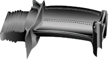
Radiusing of the lip prevents flow separation and compressor inlet distortion at low speeds during crosswind operation and take-off rotation.
There are basically two forms of shock waves: A sharp-lipped version of the pitot intake, described above for subsonic applications, performs quite well at moderate supersonic flight speeds.
However, below the shock-on-lip flight Mach number, the shock wave angle/s are less oblique, causing the streamline approaching the lip to be deflected by the presence of the cone/ramp.
This discontinuity is overcome by the normal shock moving to a lower cross-sectional area in the ducting, to decrease the Mach number at entry to the shockwave.
The intake on the SR-71 had a translating conical spike which controlled the shock wave positions to give maximum pressure recovery.
Two vertical ramps were used in the F-4 Phantom intake, the first with a fixed wedge angle of 10 degrees and the second with a variable additional deflection above Mach 1.2.
Many compressors are fitted with anti-stall systems in the form of bleed bands or variable geometry stators to decrease the likelihood of surge.
This implies a higher high-pressure shaft speed, to maintain the datum blade tip Mach number on the rear compressor stage.
Stress considerations, however, may limit the shaft speed increase, causing the original compressor to throttle-back aerodynamically to a lower pressure ratio than datum.
[16] Since the turbine cannot withstand the stoichiometric temperatures (a mixture ratio of around 15:1) in the combustion zone, the compressor air remaining after supplying the primary zone and wall-cooling film, and known as dilution air, is used to reduce the gas temperature at entry to the turbine to an acceptable level (an overall mixture ratio of between 45:1 and 130:1 is used[17]).
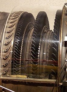
The turbine needs fewer stages than the compressor, mainly because the higher inlet temperature reduces the deltaT/T (and thereby the pressure ratio) of the expansion process.
All jet engines require high temperature gas for good efficiency, typically achieved by combusting hydrocarbon or hydrogen fuel.
After removing heat from the blade material, the air (now fairly hot) is vented, via cooling holes, into the main gas stream.
Another solution is to use an ultra-efficient turbine rim seal to pressurize the area where the cooling air passes across to the rotating disc.
This is done using primary and secondary airholes which allow a thin layer of air to cover the inner walls of the chamber preventing excessive heating.
A bypass tube is a component, usually found on turbojets that is an external pipe/s that channels air from the compressor to the propelling nozzle and afterburner section.
[19] Bypass tubes only work best at supersonic speeds from mach 2+ when the ram air effect is more than what the compressor can handle where the turbojet essentially becomes a ramjet.
[citation needed] Notable examples using bypass tubes are the Brandner E-300, Rolls-Royce Olympus and the Pratt & Whitney J58 the most common.
The fuel must be reduced with altitude to maintain the same a/f ratio as the lower ambient pressure means less weight of air entering the engine (early engine controls used a Barostat or Barometric Pressure Control depending on the type of fuel pump, fixed or variable displacement).
At high engine speeds over-speeding and over-temperaturing (going beyond the maximum allowable) must be prevented to avoid turbine blade damage.
Others, such as the HP rotor speed, will modify the pilot's request as necessary before sending a signal to the torque motor which sets the position of the FMV.
The HMU also sends fuel hydraulic signals using FADEC-controlled individual torque motors to actuators for the variable stator vanes, low and high pressure turbine clearance control, high pressure compressor clearance control and a motor for the variable bleed valves.
This is an impulse turbine impacted by burning gases from a cartridge, usually created by igniting a solid propellant similar to gunpowder.
However, the turbine is turned by burning gases - usually the fuel is isopropyl nitrate (or sometimes Hydrazine) stored in a tank and sprayed into a combustion chamber.
Most commercial aircraft and large military transport airplanes usually use what is called an auxiliary power unit (APU).
This is the typical location for an APU on most commercial airliners although some may be within the wing root (Boeing 727) or the aft fuselage (DC-9/MD80) as examples and some military transports carry their APUs in one of the main landing gear pods (C-141).
A variation of this is the APU installed in a Boeing F/A-18 Hornet; it is started by a hydraulic motor, which itself receives energy stored in an accumulator.
A nose bullet is a component of a turbojet used to divert air into the intake, in front of the accessory drive and to house the starter motor.
Depending on various conditions, such as flying through heavy rainfall, the igniter continues to provide sparks to prevent combustion from failing if the flame inside goes out.
As a result, some PRVs can adjust their spring force values using this pressure change in the bearing chamber proportionally to keep the lubricant flow constant.
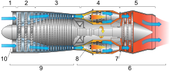
2. Low pressure compression
3. High pressure compression
4. Combustion
5. Exhaust
6. Hot section
7. Turbines Low and High pressure
8. Combustion chambers
9. Cold section
10. Air inlet