Connecting rod
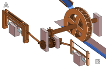
An early example of this linkage has been found at the late 3rd century Hierapolis sawmill in Roman Asia (modern Turkey) and the 6th century saw mills at Ephesus in Asia Minor (modern Turkey) and at Gerasa in Roman Syria.
The crank and connecting rod mechanism of these machines converted the rotary motion of the waterwheel into the linear movement of the saw blades.
[7] An early documentation of the design occurred sometime between 1174 and 1206 AD in the Artuqid State (modern Turkey), when inventor Al-Jazari described a machine which incorporated the connecting rod with a crankshaft to pump water as part of a water-raising machine,[8][9] though the device was more complex than typical crank and connecting rod designs.
[10]: 170 There is also documentation of cranks with connecting rods in the sketch books of Taccola from Renaissance Italy and 15th century painter Pisanello.
[11] However, most steam engines after this are double-acting, therefore the force is produced in both directions, leading to the use of a connecting rod.
[citation needed] Typically there is a pinhole bored through the bearing on the big end of the connecting rod so that lubricating oil squirts out onto the thrust side of the cylinder wall to lubricate the travel of the pistons and piston rings.
[18][19][20][21] The sideways force exerted on the piston through the connecting rod by the crankshaft can cause the cylinders to wear into an oval shape.
This significantly reduces engine performance, since the circular piston rings are unable to properly seal against the oval-shaped cylinder walls.
The simplest solution, as used in most road car engines, is for each pair of cylinders to share a crank journal, but this reduces the size of the rod bearings and means that matching (i.e. opposite) cylinders in the different banks are slightly offset along the crankshaft axis (which creates a rocking couple).
One of the most complicated examples of master-and-slave connecting rods is the 24-cylinder Junkers Jumo 222 experimental airplane engine developed for World War II.
This causes the two rods to oscillate back and forth (instead of rotating relative to each other), which reduces the forces on the bearing and the surface speed.