Control valve
The opening or closing of automatic control valves is usually done by electrical, hydraulic or pneumatic actuators.
There are three main categories of positioners, depending on the type of control signal, the diagnostic capability, and the communication protocol: pneumatic, analog, and digital.
Pressure is typically modulated between 20.7 and 103 kPa (3 to 15 psig) to move the valve from 0 to 100% position.
As the cam rotates, the beam pivots about the feedback axis to move the flapper slightly away from the nozzle.
Nozzle decreases and the relay permits the release of diaphragm casing pressure to the atmosphere, which allows the actuator stem to move upward.
Through the cam, stem movement is fed back to the beam to reposition the flapper closer to the nozzle.
When equilibrium conditions are obtained, stem movement stops and the flapper is positioned to prevent any further decrease in actuator pressure.
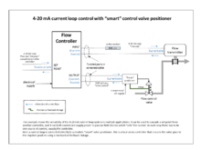
Most modern processing units use a 4 to 20 mA DC signal to modulate the control valves.
The microprocessor enables diagnostics and two-way communication to simplify setup and troubleshooting.
The microprocessor performs the position control algorithm rather than a mechanical beam, cam, and flapper assembly.
Their popularity derives from rugged construction and the many options available that make them suitable for a variety of process applications.