Crystal radio
Thus, crystal sets produce rather weak sound and must be listened to with sensitive earphones, and can receive stations only within a limited range of the transmitter.
The first crystal sets received wireless telegraphy signals broadcast by spark-gap transmitters at frequencies as low as 20 kHz.
The most common crystal used is a small piece of galena; pyrite was also often used, as it was a more easily adjusted and stable mineral, and quite sufficient for urban signal strengths.
Crystal sets represented an inexpensive and technologically simple method of receiving these signals at a time when the embryonic radio broadcasting industry was beginning to grow.
In 1922 the (then named) United States Bureau of Standards released a publication entitled Construction and Operation of a Simple Homemade Radio Receiving Outfit.
[31] This article showed how almost any family having a member who was handy with simple tools could make a radio and tune into weather, crop prices, time, news and the opera.
Pittsburgh station KDKA, owned by Westinghouse, received its license from the United States Department of Commerce just in time to broadcast the Harding-Cox presidential election returns.
Since less-affluent families could not afford to own one, newspapers and magazines carried articles on how to build a crystal radio with common household items.
To minimize the cost, many of the plans suggested winding the tuning coil on empty pasteboard containers such as oatmeal boxes, which became a common foundation for homemade radios.
In early 1920s Russia, Oleg Losev was experimenting with applying voltage biases to various kinds of crystals for the manufacturing of radio detectors.
A crystodyne could be produced under primitive conditions; it could be made in a rural forge, unlike vacuum tubes and modern semiconductor devices.
The lead point touching the semiconducting oxide coating (magnetite) on the blade formed a crude point-contact diode.
[37] It used a piezoelectric crystal earpiece (described later in this article), a ferrite core to reduce the size of the tuning coil (also described later), and a small germanium fixed diode, which did not require adjustment.
Earlier crystal radios suffered from severely reduced Q, and resulting selectivity, from the electrical load of the earphone or earpiece.
[47] Crystal radios can receive such weak signals without using amplification only due to the great sensitivity of human hearing,[3][48] which can detect sounds with an intensity of only 10−16 W/cm2.
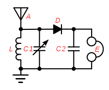
Antennas of the type commonly used with crystal sets are most effective when their length is close to a multiple of a quarter-wavelength of the radio waves they are receiving.
A popular practice in early days (particularly among apartment dwellers) was to use existing large metal objects, such as bedsprings,[14] fire escapes, and barbed wire fences as antennas.
[66] Electric charge, induced in the antenna by the radio waves, flows rapidly back and forth between the plates of the capacitor through the coil.
[4] The crystal detector worsened the problem, because it has relatively low resistance, thus it "loaded" the tuned circuit, drawing significant current and thus damping the oscillations, reducing its Q factor so it allowed through a broader band of frequencies.
If radio interference was encountered, the smaller coil would be slid further out of the larger, loosening the coupling, narrowing the bandwidth, and thereby rejecting the interfering signal.
[71] Only certain sites on the crystal surface functioned as rectifying junctions, and the device was very sensitive to the pressure of the crystal-wire contact, which could be disrupted by the slightest vibration.
[93] The spark at the buzzer's electrical contacts served as a weak source of static, so when the detector began working, the buzzing could be heard in the earphones.
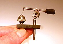
[48][95] Crystal radios have also been improvised from a variety of common objects, such as blue steel razor blades and lead pencils,[48][96] rusty needles,[97] and pennies[48] In these, a semiconducting layer of oxide or sulfide on the metal surface is usually responsible for the rectifying action.
[105] The early earphones used with wireless-era crystal sets had moving iron drivers that worked in a way similar to the horn loudspeakers of the period.
Standard headphones used in telephone work had a low impedance, often 75 Ω, and required more current than a crystal radio could supply.
Therefore, the type used with crystal set radios (and other sensitive equipment) was wound with more turns of finer wire giving it a high impedance of 2000–8000 Ω.
[109] In that case a bypass capacitor is not needed (although in practice a small one of around 0.68 to 1 nF is often used to help improve quality), but instead a 10–100 kΩ resistor must be added in parallel with the earphone's input.
[111] Similarly, modern low-impedance (8 Ω) earphones cannot be used unmodified in crystal sets because the receiver does not produce enough current to drive them.
A crystal radio tuned to a strong local transmitter can be used as a power source for a second amplified receiver of a distant station that cannot be heard without amplification.
Properly-designed and managed AM transmitters can be run to 100% modulation on peaks without causing distortion or "splatter" (excess sideband energy that radiates outside of the intended signal bandwidth).