Deflection (engineering)
In structural engineering, deflection is the degree to which a part of a long structural element (such as beam) is deformed laterally (in the direction transverse to its longitudinal axis) under a load.
A longitudinal deformation (in the direction of the axis) is called elongation.
The deflection distance of a member under a load can be calculated by integrating the function that mathematically describes the slope of the deflected shape of the member under that load.
Standard formulas exist for the deflection of common beam configurations and load cases at discrete locations.
The deflection of beam elements is usually calculated on the basis of the Euler–Bernoulli beam equation while that of a plate or shell element is calculated using plate or shell theory.
An example of the use of deflection in this context is in building construction.
Architects and engineers select materials for various applications.
Beams can vary greatly in their geometry and composition.
Some of these things make analysis difficult, but many engineering applications involve cases that are not so complicated.
Analysis is simplified if: In this case, the equation governing the beam's deflection (
being the horizontal position along the length of the beam) is interpreted as its curvature,
If, in addition, the beam is not tapered and is homogeneous, and is acted upon by a distributed load
This equation can be solved for a variety of loading and boundary conditions.
A number of simple examples are shown below.
The formulas expressed are approximations developed for long, slender, homogeneous, prismatic beams with small deflections, and linear elastic properties.
Under these restrictions, the approximations should give results within 5% of the actual deflection.
where Note that if the span doubles, the deflection increases eightfold.
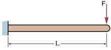
, along the span of an end loaded cantilevered beam can be calculated using:[1]
The deflection, at the free end B, of a cantilevered beam under a uniform load is given by:[1]
, along the span of a uniformly loaded cantilevered beam can be calculated using:[1]
, along the span of a center loaded simply supported beam can be calculated using:[1]
The special case of elastic deflection at the midpoint C of a beam, loaded at its center, supported by two simple supports is then given by:[1]
The elastic deflection (at the midpoint C) on a beam supported by two simple supports, under a uniform load (as pictured) is given by:[1]
, along the span of a uniformly loaded simply supported beam can be calculated using:[1]
The deflection of beams with a combination of simple loads can be calculated using the superposition principle.
The formulas supplied above require the use of a consistent set of units.
Building codes determine the maximum deflection, usually as a fraction of the span e.g. 1/400 or 1/600.
Either the strength limit state (allowable stress) or the serviceability limit state (deflection considerations among others) may govern the minimum dimensions of the member required.
When designing a steel frame to hold a glazed panel, one allows only minimal deflection to prevent fracture of the glass.
The deflected shape of a beam can be represented by the moment diagram, integrated (twice, rotated and translated to enforce support conditions).