Diesel locomotive
In 1930, Armstrong Whitworth of the United Kingdom delivered two 1,200 hp (890 kW) locomotives using Sulzer-designed engines to Buenos Aires Great Southern Railway of Argentina.
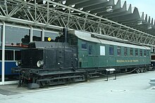
[19] In 1914, the world's first functional diesel–electric railcars were produced for the Königlich-Sächsische Staatseisenbahnen (Royal Saxon State Railways) by Waggonfabrik Rastatt with electric equipment from Brown, Boveri & Cie and diesel engines from Swiss Sulzer AG.
Several Fiat-TIBB Bo'Bo' diesel–locomotives were built for service on the 950 mm (3 ft 1+3⁄8 in) narrow gauge Ferrovie Calabro Lucane and the Società per le Strade Ferrate del Mediterrano in southern Italy in 1926, following trials in 1924–25.
Only limited success was achieved in the early twentieth century with internal combustion engined railcars, due, in part, to difficulties with mechanical drive systems.
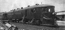
Problems related to co-ordinating the prime mover and electric motor were immediately encountered, primarily due to limitations of the Ward Leonard current control system that had been chosen.
[25] Lemp's design solved the problem of overloading and damaging the traction motors with excessive electrical power at low speeds, and was the prototype for all internal combustion–electric drive control systems.
The first milestone in that effort was delivery in early 1934 of the Winton 201A, a two-stroke, mechanically aspirated, uniflow-scavenged, unit-injected diesel engine that could deliver the required performance for a fast, lightweight passenger train.
The second milestone, and the one that got American railroads moving towards diesel, was the 1938 delivery of GM's Model 567 engine that was designed specifically for locomotive use, bringing a fivefold increase in life of some mechanical parts and showing its potential for meeting the rigors of freight service.
[34] Diesel–electric railroad locomotion entered mainline service when the Burlington Route and Union Pacific used custom-built diesel "streamliners" to haul passengers, starting in late 1934.
EMC's experimental 1800 hp B-B locomotives of 1935 demonstrated the multiple-unit control systems used for the cab/booster sets and the twin-engine format used with the later Zephyr power units.
ALCO would be the pre-eminent builder of switch engines through the mid-1930s and would adapt the basic switcher design to produce versatile and highly successful, albeit relatively low powered, road locomotives.
Diesel–mechanical propulsion is limited by the difficulty of building a reasonably sized transmission capable of coping with the power and torque required to move a heavy train.
Maintaining acceptable operating parameters was one of the principal design considerations that had to be solved in early diesel–electric locomotive development and, ultimately, led to the complex control systems in place on modern units.
The prime mover's power output is primarily determined by its rotational speed (RPM) and fuel rate, which are regulated by a governor or similar mechanism.
The propulsion system is designed to produce maximum traction motor torque at start-up, which explains why modern locomotives are capable of starting trains weighing in excess of 15,000 tons, even on ascending grades.
In fact, a consist of such units can produce more than enough drawbar pull at start-up to damage or derail cars (if on a curve) or break couplers (the latter being referred to in North American railroad slang as "jerking a lung").
In older designs, the prime mover's governor and a companion device, the load regulator, play a central role in the control system.
The governor also incorporates a separate overspeed protective mechanism that will immediately cut off the fuel supply to the injectors and sound an alarm in the cab in the event the prime mover exceeds a defined RPM.
The net effect is to adjust both the fuel rate and the load regulator position so that engine RPM and torque (and therefore power output) will remain constant for any given throttle setting, regardless of actual road speed.
Hence, the traction motors will produce their highest torque, causing the locomotive to develop maximum tractive effort, enabling it to overcome the inertia of the train.
In the mechanical transmission system that has multiple ratios such as in a gear box, if there is a hydraulic section, it is only to allow the engine to run when the train is too slow or stopped.
The reasons for this were multiple, two of the more notable being that whilst most DH locomotives achieved about the same drivetrain efficiency as DEs of around ~85% (with some early British designs being the exception), they could at the same time be built noticeably lighter for the same total power output.
In Germany and Finland however, diesel–hydraulic systems achieved a very high reliability in operation, similar to or even better than DEs, which when coupled with the DHs aforementioned technical advantages helped make it the more popular type of diesel locomotive in these countries for a long time.
Diesel–hydraulic drive is common in multiple units, with various transmission designs used including Voith torque converters, and fluid couplings in combination with mechanical gearing.
In the 21st century, designs using hydraulic transmission include Bombardier's Turbostar, Talent, RegioSwinger families; diesel engined versions of the Siemens Desiro platform, and the Stadler Regio-Shuttle.
All North American locomotives, including export models, use a standardized AAR electrical control system interconnected by a 27-pin MU cable between the units.
After revising their calculations, they concluded that the annual emissions of nitrogen oxide, a major ingredient in smog and acid rain, and soot would be by 2030 nearly twice what they originally assumed.
This brought greater efficiencies to the operator, as individual locomotives could be relatively low-powered for use as a single unit on light duties but marshaled together to provide the power needed on a heavy train.
After use a steam locomotive requires a lengthy disposal operation to perform cleaning, inspection, maintenance and refilling with water and fuel before it is ready for its next duty.
By contrast, as early as 1939 EMD was promoting its FT Series locomotive as needing no maintenance between 30-day inspections beyond refuelling and basic fluid level and safety checks which could be performed with the prime mover still running.


1 — diesel, 2 — oil filter, 3 — turning gear, 4 — water-to-fuel heater, 5 — auxiliary electric generator, 6 — hydrokinetic transmission, 7 — first gear valve (with manual shift handle), 8 — automatic transmission oil filter


