Drum brake
The modern automobile drum brake was first used in a car made by Maybach in 1900, although the principle was only later patented in 1902 by Louis Renault.
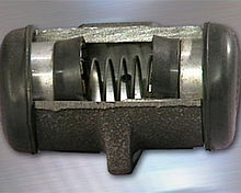
From the mid-1930s, oil pressure in a small wheel cylinder and pistons (as in the picture) operated the brakes, though some vehicles continued with purely mechanical systems for decades.
After the United States Federal Government began to regulate asbestos production, brake manufacturers had to switch to non-asbestos linings.
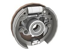
The back plate also increases the rigidity of whole set-up, supports the housing, and protects it from foreign materials like dust and other road debris.
Levers for emergency or parking brakes, and automatic brake-shoe adjuster were also added in recent years.
The brake drum is generally made of a special type of cast iron that is heat-conductive and wear-resistant.
When a driver applies the brakes, the lining pushes radially against the inner surface of the drum, and the ensuing friction slows or stops rotation of the wheel and axle, and thus the vehicle.
The crescent-shaped piece is called the Web and contains holes and slots in different shapes for return springs, hold-down hardware, parking brake linkage and self-adjusting components.
The edge of the lining table generally has three V-shaped notches or tabs on each side called nibs.
Linings must be resistant to heat and wear and have a high friction coefficient unaffected by fluctuations in temperature and humidity.
Materials that make up the brake shoe lining include, friction modifiers (which can include graphite and cashew nut shells), powdered metal such as lead, zinc, brass, aluminium and other metals that resist heat fade, binders, curing agents and fillers such as rubber chips to reduce brake noise.
"[5] The rotation of the drum can drag either one or both of the shoes into the friction surface, causing the brakes to bite harder, which increases the force holding them together.
[5] In this design, one of the brake shoes always experiences the self-applying effect, irrespective of whether the vehicle is moving forwards or backwards.
Provided the contact area of the brake shoes is large enough, which isn't always the case, the self-applying effect can securely hold a vehicle when the weight is transferred to the rear brakes due to the incline of a slope or the reverse direction of motion.
A further advantage of using a single hydraulic cylinder on the rear is that the opposite pivot may be made in the form of a double-lobed cam that is rotated by the action of the parking brake system.
[5] This design uses two actuating cylinders arranged so that both shoes use the self-applying characteristic when the vehicle is moving forwards.
Drum brake return springs give more positive action and, adjusted correctly, often have less drag when released.
[6][7] Certain heavier-duty drum brake systems compensate for load when determining wheel cylinder pressure; a feature which is rare when discs are employed (hydropneumatic suspension systems as employed on Citroën vehicles adjust brake pressure depending on load regardless of if drum or discs are used).
Land Rover have used a drum brake on the gearbox output shaft for over fifty years.
Brake drums must be large to cope with the massive forces involved, and must be able to absorb and dissipate a lot of heat.
Water between the friction surfaces and the drum can act as a lubricant and reduce braking efficiency.
Once that rate is reached, applying greater pedal pressure doesn't change it—in fact, the effects mentioned can substantially reduce it.
Grab is the opposite of fade: when the pad friction goes up, the self-assisting nature of drum brakes causes application force to go up.
If the pad friction and self-amplification are high enough, the brake stays engaged due to self-application, even when the external application force is released.
Catastrophic failure of hardware such as springs and adjusters can also cause unintended brake application or even wheel lockup.
If springs break, the shoes will be free to fall against the rotating drum, essentially causing the brakes to be applied.
This means that the very common hybrid disc/drum systems only brake with the (nearly always front) discs on light pedal pressure unless extra hardware is added.
Safety regulators sometimes recommended using vacuum hoses to suck away the dust, or enclosures with interior lighting and space to use tools inside them, but these were rare and cumbersome.
Exposure to 1-1-1-trichloroethane vapors can cause central nervous system damage, dizziness, incoordination, drowsiness, and increased reaction time.
This practice was controversial however, as it removed friction material from the brakes, reduced the life of the shoes and created hazardous asbestos dust.