Servo (radio control)
A typical servo consists of a small electric motor driving a train of reduction gears.
Any difference gives rise to an error signal in the appropriate direction, which drives the electric motor either forwards or backwards, and moving the output shaft to the commanded position.
Early servos, and a precursor device called an escapement, could only move to a limited number of set positions.
RC servos use a three-pin 0.1"-spacing jack (female) which mates to standard 0.025" square pins.
The second type is "relative" and defines the value by the percentage of time the control is active-high versus low-time.
The servo will move based on the pulses sent over the control wire, which set the angle of the actuator arm.
The servo expects a pulse every 20 ms in order to gain correct information about the angle.
Some hobby digital servos can optionally be set to another mode and "programmed", so it has the desired PID controller characteristics when it is later driven by a standard RC receiver.
Speed is expressed as a time interval that a servo requires in order to rotate the shaft through a 60° angle.
Torque is expressed as weight that can be pulled up by the servo if it hangs from a pulley with a certain radius mounted on the shaft.
Although not in accordance with either the SI or Imperial unit system, the shorthand notation is in fact quite useful, as 60° shaft rotation commands, 1 cm long shaft cranks, as well as control rod "forces" in kilogram-force range are typical in hobby RC world.
In such servos the input pulse results in a rotational speed, and the typical 1.5 ms center value is the stop position.
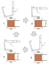
[3] Like the device used in clocks, this escapement controls the release of stored energy from a spring or rubber band.
Each signal from the transmitter operates a small solenoid that then allows a two- or four-lobed pawl to rotate.
This mechanism allows a simple keyed transmitter to give sequential control, i.e. selection between a number of defined positions at the model.