Fictitious force
[1] Fictitious forces are invoked to maintain the validity and thus use of Newton's second law of motion, in frames of reference which are not inertial.
An example in a rotating reference frame may be the impression that it is a force which seems to move objects outward toward the rim of a centrifuge or carousel.
In terms of the example of the passenger vehicle, a pseudo force seems to be active just before the body touches the backrest of the seat in the car.
It is just a consequence of the acceleration a of the physical object the non-inertial reference frame is connected to, i.e. the vehicle in this case.
It defines an inertial force as the negative of the product of mass times acceleration, just for the sake of easier calculations.
Fictitious forces, or physics whose cause is outside of the system, are no longer necessary in general relativity, since these physics are explained with the geodesics of spacetime: "The field of all possible space-time null geodesics or photon paths unifies the absolute local non-rotation standard throughout space-time.".
The Euler force is typically ignored because the variations in the angular velocity of the rotating surface of the Earth are usually insignificant.
If the Earth were to rotate twenty times faster (making each day only ~72 minutes long), people could easily get the impression that such fictitious forces were pulling on them, as on a spinning carousel.
People in temperate and tropical latitudes would, in fact, need to hold on, in order to avoid being launched into orbit by the centrifugal force.
When moving along the equator in a ship heading in an easterly direction, objects appear to be slightly lighter than on the way back.
This motion marks the phase of the fictitious centrifugal force as it is the inertia of the suitcase which plays a role in this piece of movement.
[20] Suppose a few miles further the car is moving at constant speed travelling a roundabout, again and again, then the occupants will feel as if they are being pushed to the outside of the vehicle by the (reactive) centrifugal force, away from the centre of the turn.
A classic example of a fictitious force in circular motion is the experiment of rotating spheres tied by a cord and spinning around their centre of mass.
In this case, the identification of a rotating, non-inertial frame of reference can be based upon the vanishing of fictitious forces.
In an inertial frame, fictitious forces are not necessary to explain the tension in the string joining the spheres.
In a rotating frame, Coriolis and centrifugal forces must be introduced to predict the observed tension.
For someone in the spinning frame the object moves in a complicated way that needs a centrifugal force: the blue arrow.Note: With some browsers, hitting [Esc] will freeze the motion for more detailed analysis.
[22] Fictitious forces can be considered to do work, provided that they move an object on a trajectory that changes its energy from potential to kinetic.
If they pull their hand inward toward their body, from the perspective of the rotating reference frame, they have done work against the centrifugal force.
When the weight is let go, it spontaneously flies outward relative to the rotating reference frame, because the centrifugal force does work on the object, converting its potential energy into kinetic.
This illustrates that the work done, like the total potential and kinetic energy of an object, can be different in a non-inertial frame than in an inertial one.
Many problems require use of noninertial reference frames, for example, those involving satellites[28][29] and particle accelerators.
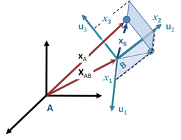
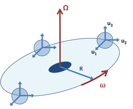
[39][40] As a related example, suppose the moving coordinate system B rotates with a constant angular speed ω in a circle of radius R about the fixed origin of inertial frame A, but maintains its coordinate axes fixed in orientation, as in Figure 3.
If the tube is spun for a long enough time, the velocity vB drops to zero as the matter comes to an equilibrium distribution.
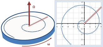
A rider on the carousel walks radially across it at a constant speed, in what appears to the walker to be the straight line path inclined at 45° in Figure 5.
Adopting the coordinate system shown in Figure 5, the trajectory is described by r(t): where the added π/4 sets the path angle at 45° to start with (just an arbitrary choice of direction), uR is a unit vector in the radial direction pointing from the centre of the carousel to the walker at the time t. The radial distance R(t) increases steadily with time according to: with s the speed of walking.
Its magnitude is 2sω, and it represents the acceleration of the walker as the edge of the carousel is neared, and the arc of the circle travelled in a fixed time increases, as can be seen by the increased spacing between points for equal time steps on the spiral in Figure 5 as the outer edge of the carousel is approached.
The rotating observer sees the walker travel a straight line from the centre of the carousel to the periphery, as shown in Figure 5.
To obtain agreement, the rotating observer has to introduce fictitious forces that appear to exist in the rotating world, even though there is no apparent reason for them, no apparent gravitational mass, electric charge or what have you, that could account for these fictitious forces.
They can be related to the general formulas already derived, namely: In this example, the velocity seen in the rotating frame is: with uR a unit vector in the radial direction.