Fire-tube boiler
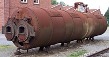
The general construction is as a tank of water penetrated by tubes that carry the hot flue gases from the fire.
This firebox has an open base to provide a large grate area and often extends beyond the cylindrical barrel to form a rectangular or tapered enclosure.
The hot gases are directed along a series of fire tubes, or flues, that penetrate the boiler and heat the water thereby generating saturated ("wet") steam.
This greatly increased the surface area for heat transfer, allowing steam to be produced at a much higher rate.
The fire itself was on an iron grating placed across this flue, with a shallow ashpan beneath to collect the non-combustible residue.
It was the invention of William Fairbairn in 1844, from a theoretical consideration of the thermodynamics of more efficient boilers that led him to increase the furnace grate area relative to the volume of water.
They are connected together through a combustion chamber – an enclosed volume contained entirely within the boiler shell – so that the flow of flue gas through the firetubes is from back to front.
Horizontal return tubular boiler (HRT) has a horizontal cylindrical shell, containing several horizontal flue tubes, with the fire located directly below the boiler's shell, usually within a brickwork setting Extensively used by Britain, before and in the early days of ironclads, the only protected place was below the waterline, sometimes under an armoured deck, so to fit below short decks, the tubes were not led back above the furnace but continued straight from it with keeping the combustion chamber in between the two.
It was not a great success and its use was being abandoned after the introduction of stronger side armouring – “the furnace crowns, being very near the water-level, are much more liable to over-heating.
It has only firetubes, functioning as a furnace and combustion chamber also, with multiple burner nozzles injecting premixed air and natural gas under pressure.
A more recent development has been the reverse flame design where the burner fires into a blind furnace and the combustion gasses double back on themselves.
Because the fire-flume boiler itself is the pressure vessel, it requires a number of safety features to prevent mechanical failure.
When the fire stops the warm chimney continues to draw additional air from the interior space until it cools.
The condensed water is corrosive due to dissolved carbon dioxide and sulfur oxides from the flue and must be neutralized before disposal.
The higher seasonal efficiency is partly because the lower boiler temperature used to condense the flue gas reduces standing losses during the off cycle.
[10] An intensive schedule of maintenance is needed to keep a high pressure railway steam boiler in safe condition.
The working life of a locomotive boiler is considerably extended if it is spared from a constant cycle of cooling and heating.
Historically, a locomotive would be kept “in steam” continuously for a period of about eight to ten days, and then allowed to cool sufficiently for a hot-water boiler washout.
[13] On reassembly care should be taken that the threaded plugs are replaced in their original holes: the tapers can vary as a result of rethreading.
The mudhole door gaskets, if of asbestos, should be renewed but those made of lead may be reused; special instructions are in force for the disposal of these harmful materials.
[12] Many boilers today make use of high temperature synthetics for the gaskets for both working environments and in preservation service as these materials are safer than the historic options.
At large maintenance facilities the boiler would have been both washed and refilled with very hot water from an external supply to bring the locomotive back to service more quickly.
Typically an annual inspection, this would require the removal and check of external fittings, such as the injectors, safety valves and pressure gauge.
High-pressure copper pipework can suffer from work hardening in use and become dangerously brittle: it may be necessary to treat these by annealing before refitting.
Before returning to use a qualified examiner will check the boiler's fitness for service and issue a safety certificate valid for ten years.