Fraunhofer diffraction equation
[1][2] The equation was named in honour of Joseph von Fraunhofer although he was not actually involved in the development of the theory.
[3] This article gives the equation in various mathematical forms, and provides detailed calculations of the Fraunhofer diffraction pattern for several different forms of diffracting apertures, specially for normally incident monochromatic plane wave.
If the aperture is in x′y′ plane, with the origin in the aperture and is illuminated by a monochromatic wave, of wavelength λ, wavenumber k with complex amplitude A(x′,y′), and the diffracted wave is observed in the unprimed x,y-plane along the positive
It can be seen from this equation that the form of the diffraction pattern depends only on the direction of viewing, so the diffraction pattern changes in size but not in form with change of viewing distance.
It can be seen that the integral in the above equations is the Fourier transform of the aperture function evaluated at frequencies.
When the diffracting aperture has circular symmetry, it is useful to use polar rather than Cartesian coordinates.
In this case, we have U(ρ,z) equal to the Fourier–Bessel or Hankel transform of the aperture function, A(ρ) Here are given examples of Fraunhofer diffraction with a normally incident monochromatic plane wave.
These derivations can be found in most standard optics books, in slightly different forms using varying notations.
The sinc function is sometimes defined as sin(πp)/πp and this may cause confusion when looking at derivations in different texts.
where ξ is the Fourier transform frequency, and the sinc function is here defined as sin(πx)/(πx) The Fourier transform frequency here is x/λz, giving
Note that the sinc function is here defined as sin(x)/(x) to maintain consistency.
When a rectangular slit of width W and height H is illuminated normally (the slit illuminated at the normal angle) by a monochromatic plane wave of wavelength λ, the complex amplitude can be found using similar analyses to those in the previous section, applied over two independent orthogonal dimensions as:[14][15][16]
If the height H of the slit is much greater than its width W, then the spacing of the vertical (along the height or the y axis) diffraction fringes is much less than the spacing of the horizontal (along the width or x axis) fringes.
If the vertical fringe spacing is so less by a relatively so large H, then the observation of the vertical fringes is so hard that a person observing the diffracted wave intensity pattern on the plane of observation or the image plane recognizes only the horizontal fringes with their narrow height.
If the illuminating beam does not illuminate the whole height of the slit, then the spacing of the vertical fringes is determined by the dimension of the laser beam along the slit height.
This function is plotted on the right, and it can be seen that, unlike the diffraction patterns produced by rectangular or circular apertures, it has no secondary rings.
This can be used in a process called apodization - the aperture is covered by a filter whose transmission varies as a Gaussian function, giving a diffraction pattern with no secondary rings.
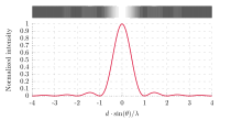
[20][21] The pattern which occurs when light diffracted from two slits overlaps is of considerable interest in physics, firstly for its importance in establishing the wave theory of light through Young's interference experiment, and secondly because of its role as a thought experiment in double-slit experiment in quantum mechanics.
Assume we have two long slits illuminated by a plane wave of wavelength λ.
The slits are in the z = 0 plane, parallel to the y axis, separated by a distance S and are symmetrical about the origin.
The incident light is diffracted by the slits into uniform spherical waves.
The waves travelling in a given direction θ from the two slits have differing phases.
The phase of the waves from the upper and lower slits relative to the origin is given by (2π/λ)(S/2)sin θ and −(2π/λ)(S/2)sin θ The complex amplitude of the summed waves is given by:[22]
A grating is defined in Principles of Optics by Born and Wolf as "any arrangement which imposes on an incident wave a periodic variation of amplitude or phase, or both".
[28] A simple grating consists of a screen with N slits whose width is significantly less than the wavelength of the incident light with slit separation of S. The complex amplitude of the diffracted wave at an angle θ is given by:[29]
Goodman[35] uses this method to derive expressions for the diffraction pattern obtained with sinusoidal amplitude and phase modulation gratings.
If the aperture is illuminated by a monochromatic plane wave incident in a direction (l0,m0, n0), the first version of the Fraunhofer equation above becomes:[36]
The equations used to model each of the systems above are altered only by changes in the constants multiplying x and y, so the diffracted light patterns will have the form, except that they will now be centred around the direction of the incident plane wave.
In all of the above examples of Fraunhofer diffraction, the effect of increasing the wavelength of the illuminating light is to reduce the size of the diffraction structure, and conversely, when the wavelength is reduced, the size of the pattern increases.
As the spread of wavelengths is increased, the number of "fringes" which can be observed is reduced.