Horn antenna
[2] Their advantages are moderate directivity, broad bandwidth, low losses, and simple construction and adjustment.
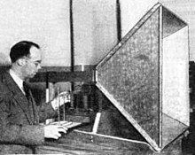
[3] One of the first horn antennas was constructed in 1897 by Bengali-Indian radio researcher Jagadish Chandra Bose in his pioneering experiments with microwaves.
[1] The input impedance is slowly varying over this wide frequency range, allowing low voltage standing wave ratio (VSWR) over the bandwidth.
This is similar to the reflection at an open-ended transmission line or a boundary between optical mediums with a low and high index of refraction, like at a glass surface.
In addition, the small aperture of the waveguide (less than one wavelength) causes significant diffraction of the waves issuing from it, resulting in a wide radiation pattern without much directivity.
[12] This acts like an impedance matching transformer, allowing most of the wave energy to radiate out the end of the horn into space, with minimal reflection.
[12] Exponential horns are used in special applications that require minimum signal loss, such as satellite antennas and radio telescopes.
in the E-field and H-field directions, making possible a wide variety of different beam profiles.
For a given frequency and horn length, there is some flare angle that gives minimum reflection and maximum gain.
The gain of the antenna is low because the small mouth approximates an open-ended waveguide, with a large impedance step.
As the angle is decreased, the amount of reflection at this site drops, and the horn's gain again increases.
This discussion shows that there is some flare angle between 0° and 90° which gives maximum gain and minimum reflection.
[22] The disadvantage is that it is far larger and heavier for a given aperture area than a parabolic dish, and must be mounted on a cumbersome turntable to be fully steerable.
[21][23][24] Since the 1970s this design has been superseded by shrouded parabolic dish antennas, which can achieve equally good sidelobe performance with a lighter more compact construction.
Another more recent horn-reflector design is the cass-horn, which is a combination of a horn with a cassegrain parabolic antenna using two reflectors.