CAN bus
Originally developed to reduce the complexity and cost of electrical wiring in automobiles through multiplexing, the CAN bus protocol has since been adopted in various other contexts.
Examples include: In recent years, the LIN bus (Local Interconnect Network) standard has been introduced to complement CAN for non-critical subsystems such as air-conditioning and infotainment, where data transmission speed and reliability are less critical.
Due to its legacy, CAN 2.0 is the most widely used protocol with a maximum payload size of eight bytes and a typical baud rate of 500 kbit/s.
[4][9][10][11] CAN FD (Flexible Data-Rate), standardized as ISO 11898-1, was developed by Bosch and released in 2012 to meet the need for increased data transfer in modern high-performance vehicles.
A node may interface to devices from simple digital logic e.g. PLD, via FPGA up to an embedded computer running extensive software.
ISO 11898-2, also called high-speed CAN (bit speeds up to 1 Mbit/s on CAN, 5 Mbit/s on CAN-FD), uses a linear bus terminated at each end with a 120 Ω resistor.
The overall termination resistance should be close to, but not less than, 100 Ω. Low-speed fault-tolerant CAN signaling operates similarly to high-speed CAN, but with larger voltage swings.
This resynchronization process is done continuously at every recessive to dominant transition to ensure the transmitter and receiver stay in sync.
The transfer layer is responsible for bit timing and synchronization, message framing, arbitration, acknowledgment, error detection and signaling, and fault confinement.
The electrical aspects of the physical layer (voltage, current, number of conductors) were specified in ISO 11898-2:2003, which is now widely accepted.
However, the mechanical aspects of the physical layer (connector type and number, colors, labels, pin-outs) have yet to be formally specified.
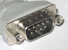
Nonetheless, several de facto standards for mechanical implementation have emerged, the most common being the 9-pin D-sub type male connector with the following pin-out: This de facto mechanical standard for CAN could be implemented with the node having both male and female 9-pin D-sub connectors electrically wired to each other in parallel within the node.
Adoption of this standard avoids the need to fabricate custom splitters to connect two sets of bus wires to a single D connector at each node.
In order to improve interoperability, many vehicle makers have generated specifications describing a set of allowed CAN transceivers in combination with requirements on the parasitic capacitance on the line.
Also, in the de facto mechanical configuration mentioned above, a supply rail is included to distribute power to each of the transceiver nodes.
ISO 11898-2 describes the electrical implementation formed from a multi-dropped single-ended balanced line configuration with resistor termination at each end of the bus.
As such the terminating resistors form an essential component of the signaling system, and are included, not just to limit wave reflection at high frequency.
which employ differential line drivers/ receivers and use a signaling system based on the differential mode voltage of the balanced line crossing a notional 0 V. Multiple access on such systems normally relies on the media supporting three states (active high, active low and inactive tri-state) and is dealt with in the time domain.
Multiple access on CAN bus is achieved by the electrical logic of the system supporting just two states that are conceptually analogous to a ‘wired AND’ network.
Interframe space contains the bit fields intermission and bus idle, and suspend transmission for error passive stations, which have been transmitter of the previous message.
[13] This document describes the general architecture of CAN in terms of hierarchical layers according to the ISO reference model for open systems interconnection (OSI) established in ISO/IEC 7498-1 and provides the characteristics for setting up an interchange of digital information between modules implementing the CAN DLL with detailed specification of the logical link control (LLC) sublayer and medium access control (MAC) sublayer.
ISO 11898-3:2006 specifies low-speed, fault-tolerant, medium-dependent interface for setting up an interchange of digital information between electronic control units of road vehicles equipped with the CAN at transmission rates above 40 kbit/s up to 125 kbit/s.
It is applicable to setting up a time-triggered interchange of digital information between electronic control units (ECU) of road vehicles equipped with CAN, and specifies the frame synchronization entity that coordinates the operation of both logical link and media access controls in accordance with ISO 11898-1, to provide the time-triggered communication schedule.
This represents an extension of ISO 11898-2, dealing with new functionality for systems requiring low-power consumption features while there is no active bus communication.
It works on extending the features, improves technical content and ensures that the current legal standards for lift control systems are met.
In most implementations, applications are expected to deploy their own security mechanisms; e.g., to authenticate incoming commands or the presence of certain devices on the network.
Failure to implement adequate security measures may result in various sorts of attacks if the opponent manages to insert messages on the bus.
[21] While passwords exist for some safety-critical functions, such as modifying firmware, programming keys, or controlling antilock brake actuators, these systems are not implemented universally and have a limited number of seed/key pairs.
Manufacturers of CAN-compatible microprocessors pay license fees to Bosch for use of the CAN trademark and any of the newer patents related to CAN FD, and these are normally passed on to the customer in the price of the chip.
Manufacturers of products with custom ASICs or FPGAs containing CAN-compatible modules need to pay a fee for the CAN Protocol License if they wish to use the CAN trademark or CAN FD capabilities.