Modbus
[1] It was originally designed for use with programmable logic controllers (PLCs),[2] but has become a de facto standard communication protocol for communication between industrial electronic devices in a wide range of buses and networks.
It was developed for industrial applications, is relatively easy to deploy and maintain compared to other standards, and places few restrictions on the format of the data to be transmitted.
[1] Modbus supports communication to and from multiple devices connected to the same cable or Ethernet network.
Many of the data types are named from industrial control of factory devices, such as ladder logic because of its use in driving relays: a single-bit physical output is called a coil, and a single-bit physical input is called a discrete input or a contact.
In 2004, they transferred the rights to the Modbus Organization[4] which is a trade association of users and suppliers of Modbus-compliant devices that advocates for the continued use of the technology.
Implementations may deploy either wireline or wireless communication, such as in the ISM radio band, and even Short Message Service (SMS) or General Packet Radio Service (GPRS).
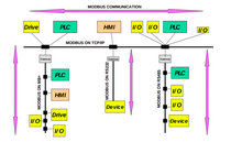
Mapping MODBUS protocol on specific buses or networks requires some additional fields, defined as the application data unit (ADU).
[6] A Modbus transaction between client and server includes:[6][10] Based on that, Modbus defines 3 PDU types:[8] Modbus defines its data model based on a series of tables of four primary types:[11] For each of the primary tables, the protocol allows individual selection of 65536 data items, and the operations of read or write of those items are designed to span multiple consecutive data items up to a data size limit which is dependent on the transaction function code.
[11] Modbus defines three types of function codes: Public, User-Defined and Reserved.
[20] With Modbus protocol on the application layer, client/server model is used for the devices on the communication channel.
[20][21] The organization's naming convention inverts the common usage of having multiple clients and only one server.
[23] In Modbus over Serial Line, the master initiates requests to the slaves in unicast or broadcast modes.
In unicast mode, the master will initiate a request to a single slave with a specific address.
[22] In this mode, a Modbus transaction includes two messages: one request from the master and one reply from the slave.
A Modbus RTU message must be transmitted continuously without inter-character hesitations.
For higher data rates, Modbus RTU recommends to use the fixed values 750 μs for t1.5 and 1.750 ms for t3.5.
Modbus ASCII messages are framed by a leading colon (":") and trailing newline (CR/LF).
For example, if Address, Function, and Data are 247, 3, 19, 137, 0, and 10, the two's complement of their sum (416) is −416; this trimmed to 8 bits is 96 (256 × 2 − 416 = 6016), giving the following 17 ASCII character frame: :F7031389000A60␍␊.
LRC is specified for use only as a checksum: because it is calculated on the encoded data rather than the transmitted characters, its 'longitudinal' characteristic is not available for use with parity bits to locate single-bit errors.
In such a case, the unit identifier is the Server Address of the device behind the gateway.
Another de facto protocol closely related to Modbus appeared later, and was defined by PLC maker April Automates, the result of a collaborative effort between French companies Renault Automation and Merlin Gerin et Cie in 1985: JBUS.
Differences between Modbus and JBUS at that time (number of entities, server stations) are now irrelevant as this protocol almost disappeared with the April PLC series, which AEG Schneider Automation bought in 1994 and then made obsolete.
JBUS supports function codes 1, 2, 3, 4, 5, 6, 15, and 16 and thus all the entities described above, although numbering is different: