Synchronization gear
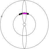
There were many practical problems, mostly arising from the inherently imprecise nature of an automatic gun's firing, the great (and varying) velocity of the blades of a spinning propeller, and the very high speed at which any gear synchronizing the two had to operate.
Design and experimentation with gun synchronization had been underway in France and Germany in 1913–1914, following the ideas of August Euler, who seems to have been the first to suggest mounting a fixed armament firing in the direction of flight (in 1910).
[3] True synchronization, though, with a machine gun's rate of fire exactly proportional to the revolutions per minute of a spinning aircraft propeller, would require an impractical level of complexity.
In practice all "real-life" synchronization gears, for which we have reliable technical details, directly fired the gun: operating it as if it were a semi-automatic weapon rather than a completely automatic one.
Many early gears used an intricate and inherently fragile bell crank and push rod linkage that could easily jam or otherwise malfunction, especially when required to work at higher speeds than it had been designed for.
Under certain circumstances this is highly undesirable.As late as 1916, pilots of the DH.2 pusher fighter had problems convincing their senior officers that the forward-firing armament of their aircraft was more effective if it was fixed to fire forward rather than being flexible.
The idea of literally "interrupting" the firing of the gun gives way (probably as the result of experience) to the principle of pulling the trigger for each successive shot, like the action of a semi-automatic weapon.
[4] After his early synchronization experiments failed, Saulnier pursued a method trusting rather less to statistics and luck by developing armoured propeller blades that would resist damage.
By March 1915, when French pilot Roland Garros approached Saulnier to arrange for this device to be installed on his Morane-Saulnier Type L, these had taken the form of steel wedges which deflected the bullets which might otherwise have damaged the propeller, or ricocheted dangerously.
[31] This crude system worked after a fashion, although the wedges diminished the propeller's efficiency, and the not inconsiderable force of the impact of bullets on the deflector blades must have put undesirable stress on the engine's crankshaft.
Initial trials indicated that the deflector wedges would not be sufficiently strong to cope with the standard steel-jacketed German ammunition, and representatives from Fokker and Pfalz, two companies already building Morane copies (although, strangely, not Schneider's LVG concern) were invited to Döberitz to inspect the mechanism and suggest ways that its action might be duplicated.
[34] Another possible explanation is that Garros's Morane, partly destroyed by fire as it was, had sufficient traces of the original synchronization gear remaining for Fokker to have guessed how it worked.
[35] For various reasons this also seems unlikely,[Note 6] and the current historical consensus points to a synchronization device having been in development by Fokker's team (including engineer Heinrich Lübbe) prior to the capture of Garros's machine.
[36] The main difference was that instead of the push rod passing directly from the engine to the gun itself, which would have required a tunnel through the firewall and fuel tank (as shown in the Saulnier patent drawings), it was driven by a shaft joining the oil pump to a small cam at the top of the fuselage.
The gear used in the production Eindecker fighters replaced the oil pump's mechanical driveshaft-based system with a large cam wheel, almost a light flywheel, driven directly from the spinning rotary engine's crankcase.
The first victory using a synchronized gun-equipped fighter is now believed to have occurred on 1 July 1915 when Leutnant Kurt Wintgens of Feldflieger Abteilung 6b, flying the Parabellum-armed Fokker M.5K/MG aircraft "E.5/15", forced down a French Morane-Saulnier Type L east of Lunéville.
By this time, the Fokker Stangensteuerung gear, which had worked reasonably well for synchronizing a single gun, firing at a modest cyclic rate through a two-bladed propeller driven by a rotary engine, was becoming obsolete.
Fokker's initial answer to this was the fitting of extra "followers" to the Stangensteuerung's large cam wheel, to (theoretically) produce the "ripple" salvo necessary to ensure that the guns were aimed at the same point on the propeller disc.
The standard machine gun of the Austro-Hungarian armed forces in 1914 was the Schwarzlose MG M.07/12 machine-gun, which operated on a "delayed blow back" system and was not suited to synchronization.
[44] Unlike the French and Italians, who were eventually able to acquire supplies of Vickers guns, the Austrians were unable to obtain sufficient quantities of "Spandaus" from their German allies and were forced to use the Schwarzlose in an application for which it was not really suited.
The first version was driven by a reduction gear attached to a rotary engine oil pump spindle as in Saulnier's design and a small impulse-generating cam was mounted externally on the port side of the forward fuselage where it was readily accessible for adjustment.
Lieutenant Victor Dibovski, an officer of the Imperial Russian Navy, while serving as a member of a mission to England to observe and report on British aircraft production methods, suggested a synchronization gear of his own design.
Twenty thousand more "Constantinesco-Colley" gun synchronization systems were fitted to British military aircraft between January and October 1918, during the period when the Royal Air Force was formed from the two earlier services on April 1, 1918.
It was based closely on the definitive Fokker Stangensteuerung gear: the main difference being that the push rod was installed within the Vickers gun, using a redundant steam tube in the cooling jacket.
[68] A spinning drive shaft, driven by the rotating crankcase of the Nieuport's 160 CV Gnome 9N Monosoupape rotary engine, drove two separately adjustable trigger motors – each imparting firing impulses to its gun by means of its own short rod.
Officially known as the Système de Synchronisation pour Vickers Type II (moteurs fixes) the Birkigt gear was later adapted to control two guns, and remained in use in French service up to the time of the Second World War.
The increased speeds of the new monoplanes of the mid to late 1930s meant that the time available to deliver a sufficient weight of fire to bring down an enemy aircraft was greatly reduced.
The retention of fuselage-mounted guns, with the additional weight of their synchronization gear (which slowed their rate of fire, albeit only slightly, and still occasionally failed, resulting in damage to propellers) became increasingly unattractive.
For example, the original 1934 specifications for the Hawker Hurricane were for a similar armament to the Gloster Gladiator: four machine-guns, two in the wings and two in the fuselage, synchronized to fire through the propeller arc.
[75] The act of shooting one's own propeller is a trope that can be found in comedic gags, like the 1965 cartoon short "Just Plane Beep"[76] starring Wile E. Coyote and the Road Runner.