Klystron
A klystron is a specialized linear-beam vacuum tube, invented in 1937 by American electrical engineers Russell and Sigurd Varian,[1] which is used as an amplifier for high radio frequencies, from UHF up into the microwave range.
Low-power klystrons are used as oscillators in terrestrial microwave relay communications links, while high-power klystrons are used as output tubes in UHF television transmitters, satellite communication, radar transmitters, and to generate the drive power for modern particle accelerators.
In a klystron, an electron beam interacts with radio waves as it passes through resonant cavities, metal boxes along the length of a tube.
The output signal can be coupled back into the input cavity to make an electronic oscillator to generate radio waves.
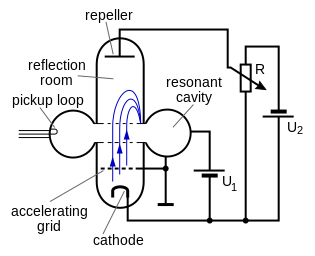
[2] A reflex klystron is an obsolete type in which the electron beam was reflected back along its path by a high potential electrode, used as an oscillator.
[6] The work of physicist W. W. Hansen was instrumental in the development of the klystron and was cited by the Varian brothers in their 1939 paper.
During the Second World War, Hansen lectured at the MIT Radiation labs two days a week, commuting to Boston from Sperry Gyroscope Company on Long Island.
During the Second World War, the Axis powers relied mostly on (then low-powered and long wavelength) klystron technology for their radar system microwave generation, while the Allies used the far more powerful but frequency-drifting technology of the cavity magnetron for much shorter-wavelength centimetric microwave generation.
Right after the war, AT&T used 4-watt klystrons in its brand new network of microwave relay links that covered the contiguous United States .
Western Union Telegraph Company also built point-to-point microwave communication links using intermediate repeater stations at about 40 mile intervals at that time, using 2K25 reflex klystrons in both the transmitters and receivers.
[9] Klystrons amplify RF signals by converting the kinetic energy in a DC electron beam into radio frequency power.
RF energy has been fed into the input cavity at, or near, its resonant frequency, creating standing waves, which produce an oscillating voltage, which acts on the electron beam.
The beam then passes through a "drift" tube, in which the faster electrons catch up to the slower ones, creating the "bunches", then through a "catcher" cavity.
Electrons entering a half-cycle later, when the polarity is opposite, encounter an electric field which opposes their motion, and are decelerated.
An electronic oscillator can be made from a klystron tube, by providing a feedback path from output to input by connecting the "catcher" and "buncher" cavities with a coaxial cable or waveguide.
Some modern klystrons include depressed collectors, which recover energy from the beam before collecting the electrons, increasing efficiency.
The reflector voltage may be varied slightly from the optimum value, which results in some loss of output power, but also in a variation in frequency.
The level of modulation applied for transmission is small enough that the power output essentially remains constant.
Tuning a klystron is delicate work which, if not done properly, can cause damage to equipment or injury to the technician due to the very high voltages that could be produced.
Special lightweight nonmagnetic (or rather very weakly diamagnetic) tools made of beryllium alloy have been used for tuning U.S. Air Force klystrons.
The drift tube is electrically insulated from the cavity walls, and DC bias is applied separately.
The DC bias on the drift tube may be adjusted to alter the transit time through it, thus allowing some electronic tuning of the oscillating frequency.
At SLAC, for example, klystrons are routinely employed which have outputs in the range of 50 MW (pulse) and 50 kW (time-averaged) at 2856 MHz.
The Arecibo Planetary Radar used two klystrons that provided a total power output of 1 MW (continuous) at 2380 MHz.