Voltage divider
For direct current and relatively low frequencies, a voltage divider may be sufficiently accurate if made only of resistors; where frequency response over a wide range is required (such as in an oscilloscope probe), a voltage divider may have capacitive elements added to compensate load capacitance.
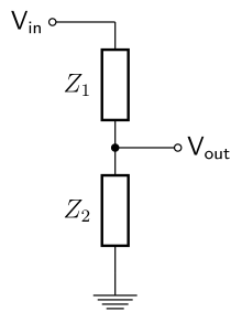
A voltage divider referenced to ground is created by connecting two electrical impedances in series, as shown in Figure 1.
If the current in the output wire is zero then the relationship between the input voltage, Vin, and the output voltage, Vout, is: Proof (using Ohm's law): The transfer function (also known as the divider's voltage ratio) of this circuit is: In general this transfer function is a complex, rational function of frequency.
Substituting Z1 = R1 and Z2 = R2 into the previous expression gives: If R1 = R2 then If Vout = 6 V and Vin = 9 V (both commonly used voltages), then: and by solving using algebra, R2 must be twice the value of R1.
This divider will then have the voltage ratio: The product τ (tau) = RC is called the time constant of the circuit.
The ratio contains an imaginary number, and actually contains both the amplitude and phase shift information of the filter.
The above equation is for non-interacting inductors; mutual inductance (as in an autotransformer) will alter the results.
Any leakage current in the capactive elements requires use of the generalized expression with two impedances.
By selection of parallel R and C elements in the proper proportions, the same division ratio can be maintained over a useful range of frequencies.
This is the principle applied in compensated oscilloscope probes to increase measurement bandwidth.
The effective source impedance coming from a divider of Z1 and Z2, as above, will be Z1 in parallel with Z2 (sometimes written Z1 // Z2), that is: (Z1 Z2) / (Z1 + Z2) = HZ1.
To obtain a sufficiently stable output voltage, the output current must either be stable (and so be made part of the calculation of the potential divider values) or limited to an appropriately small percentage of the divider's input current.
A potentiometer is used as a variable voltage divider in the volume control of many radios.
This technique is commonly used to measure the resistance of temperature sensors such as thermistors and RTDs.
Another example that is commonly used involves a potentiometer (variable resistor) as one of the resistive elements.
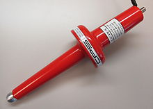
Special high-voltage resistors are used in such probes as they must be able to tolerate high input voltages and, to produce accurate results, must have matched temperature coefficients and very low voltage coefficients.
Capacitive divider probes are typically used for voltages above 100 kV, as the heat caused by power losses in resistor divider probes at such high voltages could be excessive.
If the input impedance is capacitive, a purely resistive divider will limit the data rate.
This can be roughly overcome by adding a capacitor in series with the top resistor, to make both legs of the divider capacitive as well as resistive.