Ohm's law
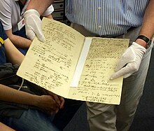
The law was named after the German physicist Georg Ohm, who, in a treatise published in 1827, described measurements of applied voltage and current through simple electrical circuits containing various lengths of wire.
Ohm explained his experimental results by a slightly more complex equation than the modern form above (see § History below).
[5] In January 1781, before Georg Ohm's work, Henry Cavendish experimented with Leyden jars and glass tubes of varying diameter and length filled with salt solution.
[8][9] Ohm did his work on resistance in the years 1825 and 1826, and published his results in 1827 as the book Die galvanische Kette, mathematisch bearbeitet ("The galvanic circuit investigated mathematically").
He used a galvanometer to measure current, and knew that the voltage between the thermocouple terminals was proportional to the junction temperature.
where x was the reading from the galvanometer, ℓ was the length of the test conductor, a depended on the thermocouple junction temperature, and b was a constant of the entire setup.
They called his work a "web of naked fancies"[11] and the Minister of Education proclaimed that "a professor who preached such heresies was unworthy to teach science.
Alternatives such as "Barlow's law", were discredited, in terms of real applications to telegraph system design, as discussed by Samuel F. B. Morse in 1855.
In this model, a solid conductor consists of a stationary lattice of atoms (ions), with conduction electrons moving randomly in it.
The development of quantum mechanics in the 1920s modified this picture somewhat, but in modern theories the average drift velocity of electrons can still be shown to be proportional to the electric field, thus deriving Ohm's law.
Ohm's work long preceded Maxwell's equations and any understanding of frequency-dependent effects in AC circuits.
In the early 20th century, it was thought that Ohm's law would fail at the atomic scale, but experiments have not borne out this expectation.
[18][19] The Drude model treats electrons (or other charge carriers) like pinballs bouncing among the ions that make up the structure of the material.
The net result is that electrons take a zigzag path due to the collisions, but generally drift in a direction opposing the electric field.
Finally, flow restrictors—such as apertures placed in pipes between points where the water pressure is measured—are the analog of resistors.
Resistors which are in series or in parallel may be grouped together into a single "equivalent resistance" in order to apply Ohm's law in analyzing the circuit.
When reactive elements such as capacitors, inductors, or transmission lines are involved in a circuit to which AC or time-varying voltage or current is applied, the relationship between voltage and current becomes the solution to a differential equation, so Ohm's law (as defined above) does not directly apply since that form contains only resistances having value R, not complex impedances which may contain capacitance (C) or inductance (L).
In a general AC circuit, Z varies strongly with the frequency parameter s, and so also will the relationship between voltage and current.
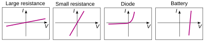
There are, however, components of electrical circuits which do not obey Ohm's law; that is, their relationship between current and voltage (their I–V curve) is nonlinear (or non-ohmic).
However, in some diode applications, the AC signal applied to the device is small and it is possible to analyze the circuit in terms of the dynamic, small-signal, or incremental resistance, defined as the one over the slope of the V–I curve at the average value (DC operating point) of the voltage (that is, one over the derivative of current with respect to voltage).
[34] Usually, the measurements of a sample resistance are carried out at low currents to prevent Joule heating.
However, even a small current causes heating(cooling) at the first(second) sample contact due to the Peltier effect.
The voltage drop across the circuit includes additionally the Seebeck thermoelectromotive force which again is again linear in current.
[36] Ohm's principle predicts the flow of electrical charge (i.e. current) in electrical conductors when subjected to the influence of voltage differences; Jean-Baptiste-Joseph Fourier's principle predicts the flow of heat in heat conductors when subjected to the influence of temperature differences.
Specifically, solving a heat conduction (Fourier) problem with temperature (the driving "force") and flux of heat (the rate of flow of the driven "quantity", i.e. heat energy) variables also solves an analogous electrical conduction (Ohm) problem having electric potential (the driving "force") and electric current (the rate of flow of the driven "quantity", i.e. charge) variables.
A similar assumption is made in the statement of Ohm's law: other things being alike, the strength of the current at each point is proportional to the gradient of electric potential.
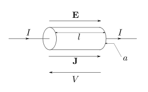
Physicists who study the electrical properties of matter at the microscopic level use a closely related and more general vector equation, sometimes also referred to as Ohm's law, having variables that are closely related to the V, I, and R scalar variables of Ohm's law, but which are each functions of position within the conductor.
If an external B-field is present and the conductor is not at rest but moving at velocity v, then an extra term must be added to account for the current induced by the Lorentz force on the charge carriers.
If the current J is alternating because the applied voltage or E-field varies in time, then reactance must be added to resistance to account for self-inductance, see electrical impedance.
Since, the electron has a very small mass compared with that of ions, we can ignore the left hand side of the above equation to write