Opto-isolator
The value of optically coupling a solid state light emitter to a semiconductor detector for the purpose of electrical isolation was recognized in 1963 by Akmenkalns, et al. (US patent 3,417,249).
Commercialization of LED technology in 1968–1970 caused a boom in optoelectronics, and by the end of the 1970s the industry developed all principal types of opto-isolators.
An optocoupled solid-state relay contains a photodiode opto-isolator which drives a power switch, usually a complementary pair of MOSFETs.
[8] Remote lightning strikes can induce surges up to 10 kV, one thousand times more than the voltage limits of many electronic components.
[9] A circuit can also incorporate high voltages by design, in which case it needs safe, reliable means of interfacing its high-voltage components with low-voltage ones.
[12] Safety, testing and approval of opto-couplers are regulated by national and international standards: IEC 60747-5-2, EN (CENELEC) 60747-5-2, UL 1577, CSA Component Acceptance Notice #5, etc.
Unlike transformers, which pass energy in both directions[note 3] with very low losses, opto-isolators are unidirectional (see exceptions) and they cannot transmit power.
[14] Unlike transformers, opto-isolators can pass DC or slow-moving signals and do not require matching impedances between input and output sides.
[16] For example, to be rated for short-term voltages of 3.75 kV and transients of 1 kV/μs, the clear polyimide sheet in the Avago ASSR-300 series is only 0.08 mm thick.
[18] Breakdown voltages of planar assemblies depend on the thickness of the transparent sheet[16] and the configuration of bonding wires that connect the dies with external pins.
The dome acts as a reflector, retaining all stray light and reflecting it onto the surface of the sensor, minimizing losses in a relatively long optical channel.
In applications where control linearity was not important, or where available current was too low for driving an incandescent bulb (as was the case in vacuum tube amplifiers), it was replaced with a neon lamp.
[28] Their resistance drops in reverse proportion to the intensity of incoming light, from virtually infinity to a residual floor that may be as low as less than a hundred Ohms.
[28] These properties made the original Vactrol a convenient and cheap automatic gain control and compressor for telephone networks.
[31] Guitarists to date prefer opto-isolated effects because their superior separation of audio and control grounds results in "inherently high quality of the sound".
[32] Performance is further compromised by slow fluctuations of resistance owing to light history, a memory effect inherent in cadmium compounds.
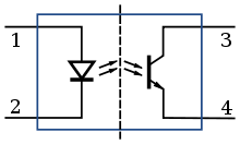
When the photodiode is reverse-biased with an external voltage source, incoming light increases the reverse current flowing through the diode.
The response times of PIN diodes lie in the subnanosecond range; overall system speed is limited by delays in LED output and in biasing circuitry.
To minimize these delays, fast digital opto-isolators contain their own LED drivers and output amplifiers optimized for speed.
[34] The Hewlett-Packard 6N137/HPCL2601 family of devices equipped with internal output amplifiers was introduced in the late 1970s and attained 10 MBd data transfer speeds.
A special class of analog opto-isolators introduced by Burr-Brown uses two photodiodes and an input-side operational amplifier to compensate for diode non-linearity.
The gate of a MOSFET requires relatively small total charge to turn on and its leakage current in steady state is very low.
[41] The earliest and the slowest but still common 4N35 opto-isolator, for example, has rise and fall times of 5 μs into a 100 Ohm load[42] and its bandwidth is limited at around 10 kilohertz - sufficient for applications like electroencephalography[6] or pulse-width motor control.
[46] Design with transistor opto-isolators requires generous allowances for wide fluctuations of parameters found in commercially available devices.
Bidirectional opto-isolators built around pairs of GaAs:Si LEDs have current transfer ratio of around 0.06% in either photovoltaic or photoconductive mode — less than photodiode-based isolators,[49] but sufficiently practical for real-world applications.