Program evaluation and review technique
PERT was originally developed by Charles E. Clark for the United States Navy in 1958; it is commonly used in conjunction with the Critical Path Method (CPM), which was also introduced in 1958.
It incorporates uncertainty by making it possible to schedule a project while not knowing precisely the details and durations of all the activities.
It is more event-oriented than start- and completion-oriented, and is used more for projects where time is the major constraint rather than cost.
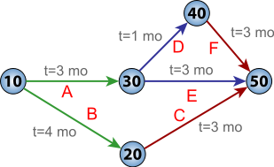
PERT offers a management tool,[2]: 497 which relies "on arrow and node diagrams of activities and events: arrows represent the activities or work necessary to reach the events or nodes that indicate each completed phase of the total project.
Although these are distinct differences, the term PERT is applied increasingly to all critical path scheduling.
"[3] PERT was developed primarily to simplify the planning and scheduling of large and complex projects.
[6] This project model was the first of its kind, a revival for the scientific management of Frederick Taylor and later refined by Henry Ford (Fordism).
Initially PERT stood for Program Evaluation Research Task, but by 1959 was renamed.
[1] In a 1959 article in The American Statistician, Willard Fazar, Head of the Program Evaluation Branch, Special Projects Office, U.S. Navy, gave a detailed description of the main concepts of PERT.
The technique is a management control tool that sizes up the outlook for meeting objectives on time; highlights danger signals requiring management decisions; reveals and defines both methodicalness and slack in the flow plan or the network of sequential activities that must be performed to meet objectives; compares current expectations with scheduled completion dates and computes the probability for meeting scheduled dates; and simulates the effects of options for decision— before decision.
Likewise, an arrow is drawn from e to g. Since there are no activities that come after f or g, it is recommended (but again not required) to connect them to a node labeled finish.
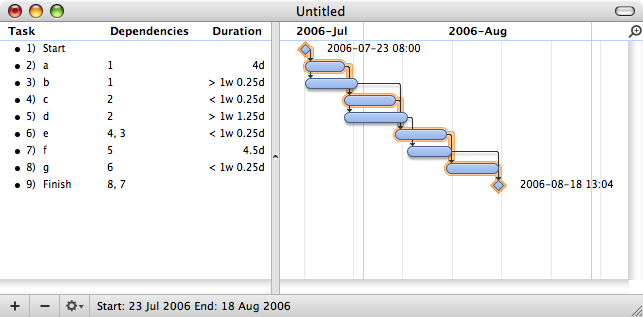
Barring any unforeseen events, the project should take 19.51 work days to complete.
Depending upon the capabilities of the data input phase of the critical path algorithm, it may be possible to create a loop, such as A -> B -> C -> A.
It is worth saving the identities of the most recently visited dozen or so nodes to help identify the problem link.
The main reason that PERT may provide inaccurate information about the project completion time is due to this schedule uncertainty.
One possible method to maximize solution robustness is to include safety in the baseline schedule in order to absorb disruptions.