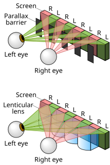
Parallax barrier

Placed in front of the normal LCD, it consists of an opaque layer with a series of precisely spaced slits, allowing each eye to see a different set of pixels, so creating a sense of depth through parallax in an effect similar to what lenticular printing produces for printed products[1][2] and lenticular lenses for other displays.

A disadvantage of the method in its simplest form is that the viewer must be positioned in a well-defined spot to experience the 3D effect.

[5] The principle of the parallax barrier was independently invented by Auguste Berthier, who published an article on stereoscopic pictures including his new idea illustrated with a diagram and pictures with purposely exaggerated dimensions of the interlaced image strips,[6] and by Frederic E. Ives, who made and exhibited a functional autostereoscopic image in 1901.

In the early 2000s, Sharp developed the electronic flat-panel application of this old technology to commercialization, briefly selling two laptops with the world's only 3D LCD screens, including the Actius RD3D.

In addition to films and computer games, the technique has found uses in areas such as molecular modelling[citation needed] and airport security.

[11] It is also being used for the navigation system in the 2010-model Range Rover,[12] allowing the driver to view (for example) GPS directions, while a passenger watches a movie.

The technology is harder to apply for 3D television sets, because of the requirement for a wide range of possible viewing angles.

A Toshiba 21-inch 3D display uses parallax barrier technology with 9 pairs of images, to cover a viewing angle of 30 degrees.

[17] The closer the parallax barrier is to the pixels, the wider the angle of separation between the left and right images.

This perturbation to the barrier pitch compensates for the fact that the edges of a display are viewed at a different angle to that of the centre, it enables the left and right images target the eyes appropriately from all positions of the screen.

In a parallax barrier system for a high-resolution display, the performance (brightness and crosstalk) can be simulated by Fresnel diffraction theory.

Therefore, the resolution of the display is reduced, and so it can be advantageous to make a parallax barrier that can be switched on when 3D is needed or off when a 2D image is required.

Adjustment of the angle at which the left and right views are projected can be done by mechanically or electronically shifting the parallax barrier relative to the pixels.

[24] A technique to quantify the level of crosstalk from a 3D display involves measuring the percentage of light that deviates from one view to the other.

[18] Theoretical simulations of diffraction have been found to be a good predictor of experimental crosstalk measurements in emulsion parallax barrier systems.

These simulations predict that the amount of crosstalk caused by the parallax barrier will be highly dependent on the sharpness of the edges of the slits.

The diffraction simulations also suggest that if the parallax barrier slit edges had a transmission that decreases over a 10 micrometers region, then crosstalk could become as 0.1.

Comparison of parallax-barrier and lenticular autostereoscopic displays . Note: The figure is not to scale. Lenticules can be modified and more pixels can be used to make automultiscopic displays
Berthier's diagram: A-B=glass plate, with a-b=opaque lines, P=Picture, O=Eyes, c-n=blocked and allowed views ( Le Cosmos 05-1896)
A cross sectional diagram of a parallax barrier, with all its important dimensions labelled.
a). If the parallax barrier had exactly twice the pitch of the pixels, it would be aligned in synchronisation with the pixel across whole of the display. The left and right views would be emitted at the same angles all across the display. It can be seen that the viewer’s left eye does not receive the left image from all points on the screen. The display does not work well. b). If the barrier pitch is modified, the views can be made to converge, such that the viewer sees the correct images from all points on the screen. c). Shows the calculation which determines the pitch of the barrier that is needed. p is the pixel pitch, d is the pixel barrier separation, f is the barrier pitch.
An autostereoscopic display that is switchable between 2D and 3D. In 3D mode the parallax barrier is formed with an LC cell, in a similar way to how an image is created on an LCD. In 2D mode the LC cell is switched into a transparent state such that no parallax barrier exists. In this case the light from the LCD pixels can go in any direction and the display acts like a normal 2D LCD.
A diagram showing how 3D can be created using time multiplexed parallax barrier. In the first time cycle, the slits in the barrier are arranged in a conventional way for a 3D display, and the left and right eyes see the left and right eye pixels. In the next time cycle, the positions of the slits are changed (possible because each slit is formed with an LC shutter). In the new barrier position, the right eye can see the pixels that were hidden in the previous time cycle. These uncovered pixels are set to show the right image (rather than the left image which they showed in the previous time cycle). The same is true for the left eye. This cycling between the two positions of the barrier, and the interlacing pattern, enables both eyes to see the correct image from half the pixels in the first time cycle, and the correct image from the other half of the pixels in the other time cycle. The cycles repeats every 50th of a second so that the switching is not noticeable to the user, but user has the impression that the appearance each eye is seeing an image from all the pixels. Consequently, the display appears to have full resolution.
Measurement of crosstalk in 3D displays. Crosstalk is the percentage of light from one view leaking to the other view. The measurements and calculations above show how crosstalk is defined when measuring crosstalk in the left image. Diagrams a) sketch the intensity measurements that need to be made for different outputs from the 3D display. Table b) describe their purpose. Equation c) is used to derive the crosstalk. It is the ratio of the light leakage from the right image into the left image but note that the imperfect black level of the LCD is subtracted out from the result so that it does not change the crosstalk ratio.
The principle of crosstalk correction.