Phase-shift keying
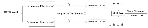
The demodulator, which is designed specifically for the symbol-set used by the modulator, determines the phase of the received signal and maps it back to the symbol it represents, thus recovering the original data.
CPSK requires a complicated demodulator, because it must extract the reference wave from the received signal and keep track of it, to compare each sample to.
Because the symbols are encoded in the difference in phase between successive samples, this is called differential phase-shift keying (DPSK).
DPSK can be significantly simpler to implement than ordinary PSK, as it is a 'non-coherent' scheme, i.e. there is no need for the demodulator to keep track of a reference wave.
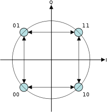
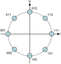
In PSK, the constellation points chosen are usually positioned with uniform angular spacing around a circle.
In this way, the moduli of the complex numbers they represent will be the same and thus so will the amplitudes needed for the cosine and sine waves.
In the presence of an arbitrary phase-shift introduced by the communications channel, the demodulator (see, e.g. Costas loop) is unable to tell which constellation point is which.
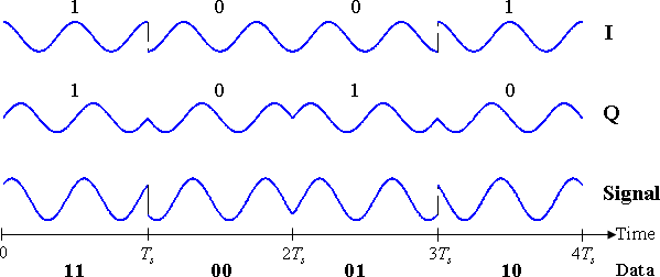
In the specific form, binary data is often conveyed with the following signals:[citation needed] where f is the frequency of the base band.
Given that radio communication channels are allocated by agencies such as the Federal Communications Commission giving a prescribed (maximum) bandwidth, the advantage of QPSK over BPSK becomes evident: QPSK transmits twice the data rate in a given bandwidth compared to BPSK - at the same BER.
As with BPSK, there are phase ambiguity problems at the receiving end, and differentially encoded QPSK is often used in practice.
Writing the symbols in the constellation diagram in terms of the sine and cosine waves used to transmit them: This yields the four phases π/4, 3π/4, 5π/4 and 7π/4 as needed.
Hence, the signal constellation consists of the signal-space 4 points The factors of 1/2 indicate that the total power is split equally between the two carriers.
When the signal is low-pass filtered (as is typical in a transmitter), these phase-shifts result in large amplitude fluctuations, an undesirable quality in communication systems.
As mentioned for BPSK and QPSK there is an ambiguity of phase if the constellation is rotated by some effect in the communications channel through which the signal passes.
Analysis shows that differential encoding approximately doubles the error rate compared to ordinary
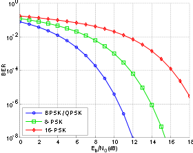
Furthermore, this analysis (and the graphical results below) are based on a system in which the only corruption is additive white Gaussian noise (AWGN).
Instead of demodulating as usual and ignoring carrier-phase ambiguity, the phase between two successive received symbols is compared and used to determine what the data must have been.
Note that this is subtly different from just differentially encoded PSK since, upon reception, the received symbols are not decoded one-by-one to constellation points but are instead compared directly to one another.
The probability of error for DPSK is difficult to calculate in general, but, in the case of DBPSK it is: which, when numerically evaluated, is only slightly worse than ordinary BPSK, particularly at higher
Using DPSK avoids the need for possibly complex carrier-recovery schemes to provide an accurate phase estimate and can be an attractive alternative to ordinary PSK.
In further processing, a photodiode is used to transform the optical field into an electric current, so the information is changed back into its original state.
For DQPSK though, the loss in performance compared to ordinary QPSK is larger and the system designer must balance this against the reduction in complexity.
The performance degradation is a result of noncoherent transmission – in this case it refers to the fact that tracking of the phase is completely ignored.
These error rates are lower than those computed in fading channels, hence, are a good theoretical benchmark to compare with.
Owing to PSK's simplicity, particularly when compared with its competitor quadrature amplitude modulation, it is widely used in existing technologies.
The wireless LAN standard, IEEE 802.11b-1999,[10][11] uses a variety of different PSKs depending on the data rate required.
Because of its simplicity, BPSK is appropriate for low-cost passive transmitters, and is used in RFID standards such as ISO/IEC 14443 which has been adopted for biometric passports, credit cards such as American Express's ExpressPay, and many other applications.
The chipsets used in new satellite set top boxes, such as Broadcom's 7000 series support 8PSK and are backward compatible with the older standard.
[17] The curves of mutual information saturate to the number of bits carried by each symbol in the limit of infinite signal to noise ratio
On the contrary, in the limit of small signal to noise ratios the mutual information approaches the AWGN channel capacity, which is the supremum among all possible choices of symbol statistical distributions.