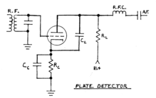
Plate detector (radio)
In electronics, a plate detector (anode bend detector, grid bias detector) is a vacuum tube circuit in which an amplifying tube having a control grid is operated in a non-linear region of its grid voltage versus plate current transfer characteristic, usually near plate current cutoff, to demodulate amplitude modulated carrier signal.
In 1927, the advent of screen grid tubes permitted much more radio frequency amplification before the detector stage than previously practically possible.
This made plate detector circuits more practical for low-priced radios sold during the depths of the Great Depression.
In these receivers, volume control is often accomplished by providing variable cathode bias of one or more stages prior to the detector.
The most common connection of the potentiometer (typically 4 kΩ to 15 kΩ linear taper) is as follows: To set a limit on the ability of the volume control to reduce the bias on the stages that it controls, the potentiometer is often equipped with a mechanical rotation limit facility that prevents the resistance from being reduced below a specific amount.
[7][8] The circuit is operated in the region where grid current does not occur during any portion of the carrier frequency cycle, thus the name "Infinite Impedance Detector".
The positive-going 180 degrees of the carrier input signal causes a substantial increase of cathode or source current above the amount set by the bias, and the negative-going 180 degrees of the carrier cycle causes a very little decrease of cathode current below the level set by the bias.
Negative feedback takes place at the recovered modulation frequencies, reducing distortion.