Plug flow reactor model
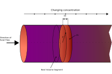
Fluid going through a PFR may be modeled as flowing through the reactor as a series of infinitely thin coherent "plugs", each with a uniform composition, traveling in the axial direction of the reactor, with each plug having a different composition from the ones before and after it.
Each plug of differential volume is considered as a separate entity, effectively an infinitesimally small continuous stirred tank reactor, limiting to zero volume.
In the ideal PFR, the residence time distribution is therefore a Dirac delta function with a value equal to
The stationary PFR is governed by ordinary differential equations, the solution for which can be calculated providing that appropriate boundary conditions are known.
The PFR model works well for many fluids: liquids, gases, and slurries.
Although turbulent flow and axial diffusion cause a degree of mixing in the axial direction in real reactors, the PFR model is appropriate when these effects are sufficiently small that they can be ignored.
In the simplest case of a PFR model, several key assumptions must be made in order to simplify the problem, some of which are outlined below.
Assumptions: A material balance on the differential volume of a fluid element, or plug, on species i of axial length dx between x and x + dx gives: Accumulation is 0 under steady state; therefore, the above mass balance can be re-written as follows: 1.
[1] where: The flow linear velocity, u (m/s) and the concentration of species i, Ci (mol/m3) can be introduced as: where
[1] When like terms are cancelled and the limit dx → 0 is applied to Equation 2 the mass balance on species i becomes 3.
,[1] The temperature dependence of the reaction rate, r, can be estimated using the Arrhenius equation.
, is the average amount of time a discrete quantity of reagent spends inside the tank.
, where CA0 is the concentration of species A at the inlet to the reactor, appearing from the integration boundary condition.
PFRs are used to model the chemical transformation of compounds as they are transported in systems resembling "pipes".
The "pipe" can represent a variety of engineered or natural conduits through which liquids or gases flow.
A typical plug flow reactor could be a tube packed with some solid material (frequently a catalyst).
[5] Real plug flow reactors with non-ideal behavior have also been modelled.
[6] To predict the exact behavior of a vessel as a chemical reactor, RTD or stimulus response technique is used.
The tracer technique, the most widely used method for the study of axial dispersion, is usually used in the form of:[7] The RTD is determined experimentally by injecting an inert chemical, molecule, or atom, called a tracer, into the reactor at some time t = 0 and then measuring the tracer concentration, C, in the effluent stream as a function of time.
[4] The RTD curve of fluid leaving a vessel is called the E-Curve.
This curve is normalized in such a way that the area under it is unity: The mean age of the exit stream or mean residence time is: When a tracer is injected into a reactor at a location more than two or three particle diameters downstream from the entrance and measured some distance upstream from the exit, the system can be described by the dispersion model with combinations of open or close boundary conditions.
[3] For such a system where there is no discontinuity in type of flow at the point of tracer injection or at the point of tracer measurement, the variance for open-open system is: Where, which represents the ratio of rate of transport by convection to rate of transport by diffusion or dispersion.
Vessel dispersion number is defined as: The variance of a continuous distribution measured at a finite number of equidistant locations is given by: Where mean residence time τ is given by: Thus (σθ)2 can be evaluated from the experimental data on C vs. t and for known values of
[8][9][3] From the safety technical point of view the PFR has the advantages that [10] The main problems lies in difficult and sometimes critical start-up and shut down operations.