Power electronics
Uno Lamm developed a mercury valve with grading electrodes making them suitable for high voltage direct current power transmission.
[1] Julius Edgar Lilienfeld proposed the concept of a field-effect transistor in 1926, but it was not possible to actually construct a working device at that time.
[2] In 1947, the bipolar point-contact transistor was invented by Walter H. Brattain and John Bardeen under the direction of William Shockley at Bell Labs.
In 1956, the silicon controlled rectifier (SCR) was introduced by General Electric, greatly increasing the range of power electronics applications.
[4] He developed the state-space averaging method of analysis and other tools crucial to modern power electronics design.
[6] Subsequently, Dawon Kahng led a paper demonstrating a working MOSFET with their Bell Labs team in 1960.
[10] From 1974, Yamaha, JVC, Pioneer Corporation, Sony and Toshiba began manufacturing audio amplifiers with power MOSFETs.
Formerly, the mercury arc valve, the high-vacuum and gas-filled diode thermionic rectifiers, and triggered devices such as the thyratron and ignitron were widely used in power electronics.
Devices such as gate turn-off thyristors, BJT and MOSFET transistors provide full switching control and can be turned on or off without regard to the current flow through them.
Faster switching devices minimize energy lost in the transitions from on to off and back but may create problems with radiated electromagnetic interference.
Practical devices have a non-zero voltage drop and dissipate power when on, and take some time to pass through an active region until they reach the "on" or "off" state.
Power electronic devices may have to dissipate tens or hundreds of watts of waste heat, even switching as efficiently as possible between conducting and non-conducting states.
High power semiconductors require specialized heat sinks or active cooling systems to manage their junction temperature; exotic semiconductors such as silicon carbide have an advantage over straight silicon in this respect, and germanium, once the main-stay of solid-state electronics is now little used due to its unfavorable high-temperature properties.
Applications include adjustable speed drives (ASD), uninterruptible power supplies (UPS), Flexible AC transmission systems (FACTS), voltage compensators, and photovoltaic inverters.
Three-phase VSIs are used in applications that require sinusoidal voltage waveforms, such as ASDs, UPSs, and some types of FACTS devices such as the STATCOM.
The normal operation of CSIs and VSIs can be classified as two-level inverters, due to the fact that power switches connect to either the positive or to the negative DC bus.
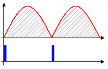
Square-wave mode offers simplicity, while PWM can be implemented in several different ways and produces higher quality waveforms.
The carrier-based PWM technique compares the AC output waveform, vc, to a carrier voltage signal, vΔ.
[19] If the over-modulation region, ma, exceeds one, a higher fundamental AC output voltage will be observed, but at the cost of saturation.
The full-bridge inverter is similar to the half bridge-inverter, but it has an additional leg to connect the neutral point to the load.
The output voltage for this modulation technique is more or less sinusoidal, with a fundamental component that has an amplitude in the linear region of less than or equal to one[17] vo1 =vab1= vi • ma.
Unlike the bipolar PWM technique, the unipolar approach uses states 1, 2, 3, and 4 from Table 2 to generate its AC output voltage.
[17] Due to the absence of freewheeling diodes, the power circuit is reduced in size and weight, and tends to be more reliable than VSIs.
Normal operation of CSIs and VSIs can be classified as two-level inverters because the power switches connect to either the positive or the negative DC bus.
Due to added complexity and the number of semiconductor devices, multilevel inverters are currently more suitable for high-power high-voltage applications.
This configuration requires no real power consumption, as it is fully fed by the line; the DC link is simply a capacitor that is kept at a constant voltage by the control system.
Conversely, VAR compensation is possible in a similar configuration where output currents lead line voltages to improve the overall power factor.
Power electronic devices are utilized in these systems to convert the generated ac voltages into high-voltage direct current (HVDC).
Germany and parts of Hawaii, California, and New Jersey require costly studies to be conducted before approving new solar installations.
Relatively small-scale ground- or pole-mounted devices create the potential for a distributed control infrastructure to monitor and manage the flow of power.