Monopole antenna
The most common form is the quarter-wave monopole, in which the antenna is approximately one quarter of the wavelength of the radio waves.
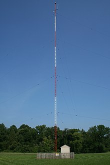
[4][3] Large monopoles are the main transmitting antennas used in the lower frequencies below 3 MHz, the MF, LF, and VLF bands, because the radio propagation mode used in these bands, ground waves, requires a vertically polarized antenna with good horizontal radiation characteristics.
[12] At lower frequencies in the LF and VLF band, the tallest antenna masts that can be practically constructed are electrically short, significantly shorter than one-quarter wavelength.
[25][26] A monopole type widely used in wireless devices and cell phones operating at microwave frequencies is the inverted F antenna (IFA).
The monopole is also called a Marconi antenna,[5][6] although Alexander Popov independently invented it at about the same time for his lightning detection receiver.
In 1901 he achieved transatlantic radio transmission using a monopole transmitting antenna consisting of 50 vertical wires suspended in a fan shape from a support cable between 60 meter poles.
In October 1866 Mahlon Loomis demonstrated communication between two grounded 183-meter (600-foot) wire aerials supported by kites on mountaintops 22 kilometres (14 miles) apart.
Marconi's new antenna functioned as a quarter-wave monopole[36] which radiated with a wavelength of approximately four times its height.
[38] Marconi, who was self-educated in physics, didn't understand any of this at the time;[38] he merely discovered an empirical relation between antenna height and transmission distance.
[42][43] Around 1898 André Blondel used image theory to show that the monopole had the same radiation pattern as a vertical dipole antenna of twice the length.
[53] When radio broadcasting began in the MF band in the early 1920s, the typical transmitting antenna was the T-antenna.
[56] He found that the radiation resistance increased to a maximum at a length of a half wavelength, so a mast around that length had an input impedance that was much higher than the ground resistance, reducing the fraction of transmitter power that was lost in the ground system, eliminating the need for capacitive toploads.
In a second paper the same year he showed that the amount of power radiated horizontally in ground waves reached a maximum at a mast height of 5/8 wavelength (.625
Due to these end conditions the monopole is resonant (has pure resistive input impedance) at a length of a quarter wavelength or multiples of it.
A transmitting antenna will absorb all the power applied to its feedpoint only if it is conjugate impedance matched to the feedline from the transmitter.
First, it reflects the downward directed radio waves from the rod, increasing the power radiated above the ground.
Second, it acts as a capacitor plate, receiving the displacement current (alternating electric field) from the rod, returning it to the ground side of the feedline.
Over a perfectly conducting infinite ground plane, the input impedance of a monopole is half that of a center-fed dipole twice the length.
A monopole antenna is resonant (has pure resistive input impedance, no reactance) at a series of frequencies, which depend on its length
The resonant frequencies can be calculated by a derivation similar to that in the previous section, but it is easier to note that a standing wave has a node at intervals of one-half wavelength.
[103][104] When fed at the bottom, due to the current node and voltage antinode there the antenna has a very high input resistance, which is difficult to calculate.
), the half-wave monopole, because their radiation patterns consist of a single lobe in horizontal directions, perpendicular to the antenna axis.
An empirical formula for the actual resonant length of the quarter-wave monopole as a function of element length-to-diameter ratio
As the antenna is made longer, the pattern divides into more lobes, with nulls (directions of zero radiated power) between them.
[1][129] When mounted on the Earth, due to the finite resistance of the soil the portion of the ground wave propagating horizontally in contact with the ground is attenuated exponentially and vanishes at long distances, so in the (far field) radiation pattern the radiated power declines smoothly to zero at the horizon (zero elevation angle).
[136][4] The gain figures given in the table above are never approached in practice; they would only be achieved if the antenna was mounted over an infinite perfectly conducting ground plane.
at the front of the equation means that the electric and magnetic fields leave the antenna 90° out of phase with the feed current.
A monopole shorter than the fundamental resonance length of a quarter-wavelength at its operating frequency is called electrically short.
Even a very short rod a small fraction of a wavelength long can be impedance matched to a transmitter so it absorbs all the power from the feedline.
In the VLF band the huge top-loaded wire monopoles used by megawatt military transmitters are often less than 0.01 wavelengths high and have radiation resistance of less than 0.1 ohm.