RS-232
Thanks to their simplicity and past ubiquity, however, RS-232 interfaces are still used—particularly in industrial CNC machines, networking equipment and scientific instruments where a short-range, point-to-point, low-speed wired data connection is fully adequate.
The resulting common problems were non-standard pin assignment of circuits on connectors, and incorrect or missing control signals.
[citation needed] Later personal computers (and other devices) started to make use of the standard so that they could connect to existing equipment.
[citation needed] Related ITU-T standards include V.24 (circuit identification) and ITU-T/CCITT V.28 [de] (signal voltage and timing characteristics).
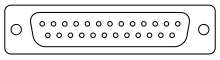
[citation needed] In revision D of EIA-232, the D-subminiature connector was formally included as part of the standard (it was only referenced in the appendix of RS-232-C).
The voltage range was extended to ±25 volts, and the circuit capacitance limit was expressly stated as 2500 pF.
[7] Specification document revision history: Because RS-232 is used beyond the original purpose of interconnecting a terminal with a modem, successor standards have been developed to address the limitations.
Each data or control circuit only operates in one direction, that is, signaling from a DTE to the attached DCE or the reverse.
For data transmission lines (TxD, RxD, and their secondary channel equivalents), logic one is represented as a negative voltage and the signal condition is called "mark".
Many RS-232 driver chips have inbuilt charge pump circuitry to produce the required voltages from a 3 or 5 volt supply.
RS-232 drivers and receivers must be able to withstand indefinite short circuits to the ground or to any voltage level up to ±25 volts.
These also protect the device's internal circuitry from short circuits or transients that may appear on the RS-232 interface, and provide sufficient current to comply with the slew rate requirements for data transmission.
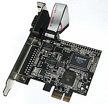
For example, on the original IBM PC, a male D-sub was an RS-232-C DTE port (with a non-standard current loop interface on reserved pins), but the female D-sub connector on the same PC model was used for the parallel "Centronics" printer port.
Since the standard definitions are not always correctly applied, it is often necessary to consult documentation, test connections with a breakout box, or use trial and error to find a cable that works when interconnecting two devices.
Poor-quality cables can cause false signals by crosstalk between data and control lines (such as Ring Indicator).
Gender changers and null modem cables are not mentioned in the standard, so there is no officially sanctioned design for them.
In many computer serial ports, a hardware interrupt is generated when the RI signal changes state.
However, due to the possibility of changing line quality, delays in processing of data, etc., there is a need for symmetric, bidirectional flow control.
A symmetric alternative providing flow control in both directions was developed and marketed in the late 1980s by various equipment manufacturers.
This scheme was eventually codified in version RS-232-E (actually TIA-232-E by that time) by defining a new signal, "RTR (Ready to Receive)", which is CCITT V.24 circuit 133.
[15] In this scheme, commonly called "RTS/CTS flow control" or "RTS/CTS handshaking" (though the technically correct name would be "RTR/CTS"), the DTE asserts RTS whenever it is ready to receive data from the DCE, and the DCE asserts CTS whenever it is ready to receive data from the DTE.
When only hardware flow control is required in addition to two-way data, the RTS and CTS lines are added in a 5-wire version.
Loopback testing is often performed with a specialized DTE called a bit error rate tester (or BERT).
Alternatively, the DTE can provide a clock signal, called transmitter timing (TT, pin 24) for transmitted data.
TT may be generated by looping ST back with an appropriate phase change to align it with the transmitted data.
ST loop back to TT lets the DTE use the DCE as the frequency reference, and correct the clock to data timing.
The original IBM PC serial port card implemented a 20 mA current-loop interface, which was never emulated by other suppliers of plug-compatible equipment.
Other serial interfaces similar to RS-232: The International Telecommunication Union publishes standard ITR-R V.24 (formerly CCITT standard V.24), "List of Definitions for Interchange Circuits between Data Terminal Equipment (DTE) and Data Circuit-Terminating Equipment (DCE)" with circuit definitions compatible to those in EIA RS 232.
When developing or troubleshooting systems using RS-232, close examination of hardware signals can be important to find problems.
A serial line analyzer is a device similar to a logic analyzer but specialized for RS-232's voltage levels, connectors, and, where used, clock signals; it collects, stores, and displays the data and control signals, allowing developers to view them in detail.