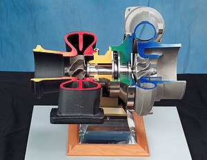
Centrifugal compressor
Bernoulli's fluid dynamic principle plays an important role in understanding vaneless stationary components like an inlet.
This is identical to an axial compressor with the exception that the gases can reach higher energy levels through the impeller's increasing radius.
When the diffuser discharges into an annular bend the collector may be referred to as a combustor inlet (as used in jet engines or gas turbines) or a return-channel (as used in an online multi-stage compressor).
In engineering situations assuming adiabatic flow, this equation can be written in the form: Equation-1.4 where: Over the past 100 years, applied scientists including Stodola (1903, 1927–1945),[7] Pfleiderer (1952),[8] Hawthorne (1964),[9] Shepherd (1956),[1] Lakshminarayana (1996),[10] and Japikse (many texts including citations),[2][11][citation needed][12] have educated young engineers in the fundamentals of turbomachinery.
These understandings apply to all dynamic, continuous-flow, axisymmetric pumps, fans, blowers, and compressors in axial, mixed-flow and radial/centrifugal configurations.
[14] Mathematicians and physicists who established the foundations of this aero-thermo domain include:[15][16] Isaac Newton, Daniel Bernoulli, Leonhard Euler, Claude-Louis Navier, George Stokes, Ernst Mach, Nikolay Yegorovich Zhukovsky, Martin Kutta, Ludwig Prandtl, Theodore von Kármán, Paul Richard Heinrich Blasius, and Henri Coandă.
[1][14] Key contributors of technical achievements that pushed the practical application of turbomachinery forward include:[15][16] Denis Papin,[17] Kernelien Le Demour, Daniel Gabriel Fahrenheit, John Smeaton, Dr. A. C. E. Rateau,[18] John Barber, Alexander Sablukov, Sir Charles Algernon Parsons, Ægidius Elling, Sanford Alexander Moss, Willis Carrier, Adolf Busemann, Hermann Schlichting, Frank Whittle and Hans von Ohain.
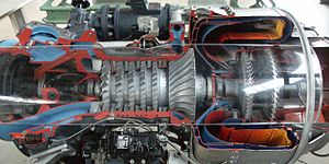
The 1940s-era German Heinkel HeS 011 experimental engine was the first aviation turbojet to have a compressor stage with radial flow-turning part-way between none for an axial and 90 degrees for a centrifugal.
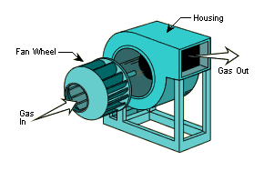
[1] In contrast to centrifugal fans, compressors operate at higher speeds to generate greater pressure rises.
In contrast, fans or blowers are often considered to have density increases of less than five percent and peak relative fluid velocities below Mach 0.3.
As turbomachinery became more common, standards have been created to guide manufacturers to assure end-users that their products meet minimum safety and performance requirements.
Assuming dry air, and the ideal gas equation of state and an isentropic process, there is enough information to define the pressure ratio and efficiency for this one point.
Figure 5.2, a centrifugal compressor performance map (either test or estimated), shows the flow, pressure ratio for each of 4 speed-lines (total of 23 data points).
Centrifugal compressor performance presented in this form provides enough information to match the hardware represented by the map to a simple set of end-user requirements.
Pressure ratio and flow are the main parameters[15][31][33][34] needed to match the Figure 5.2 performance map to a simple compressor application.
For this reason, it is only necessary to summarize that in the ideal case, the lowest specific fuel consumption would occur when the centrifugal compressor's peak efficiency curve coincides with the gas turbine's required operation line.
In contrast to gas turbines, most other applications (including industrial) need to meet a less stringent set of performance requirements.
Historically, centrifugal compressors applied to industrial applications were needed to achieve performance at a specific flow and pressure.
Modern industrial compressors are often needed to achieve specific performance goals across a range of flows and pressures; thus taking a significant step toward the sophistication seen in gas turbine applications.
If the compressor represented in Figure 5.2 is used in a simple application, any point (pressure and flow) within the 76% efficiency would provide very acceptable performance.
Surge - is a low flow phenomenon where the impeller cannot add enough energy to overcome the system resistance or backpressure.
When reversed flow reduces to a low enough level, the impeller recovers and regains stability for a short moment at which point the stage may surge again.
These cyclic events cause large vibrations, increase temperature and change rapidly the axial thrust.
As stated earlier, the reason for this is that the high-speed line in Figure 5.2 exhibits a stalling characteristic or positive slope within that range of flows.
In most cases the reason for this is that close to Mach 1 velocities have been reached somewhere within the impeller and/or diffuser generating a rapid increase in losses.
Real choke phenomena is a function of compressibility as measured by the local Mach number within an area restriction within the centrifugal pressure stage.
Many industrial and commercial multistage compressor performance maps exhibits this same vertical characteristic for a different reason related to what is known as stage stacking.
Specifically, pressure rise (p), flow (Q), angular speed (N), power (P), density (ρ), diameter (D), viscosity (μ) and elasticity (e).
[10][39] Until recently, limitations in computational power, forced these equations to be simplified to an inviscid two-dimensional problem with pseudo losses.
Ideally, centrifugal compressor impellers have thin air-foil blades that are strong, each mounted on a light rotor.