Epicyclic gearing
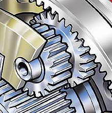
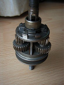
Simple planetary gears have one sun, one ring, one carrier, and one planet set.
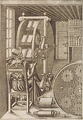
Around 500 BC, the Greeks invented the idea of epicycles, of circles travelling on the circular orbits.
With this theory Claudius Ptolemy in the Almagest in 148 AD was able to approximate planetary paths observed crossing the sky.
Accurate predictions of the movement of the Sun, Moon, and the five planets, Mercury, Venus, Mars, Jupiter, and Saturn, across the sky assumed that each followed a trajectory traced by a point on the planet gear of an epicyclic gear train.
Two facing gears were rotated around slightly different centers; one drove the other, not with meshed teeth but with a pin inserted into a slot on the second.
[citation needed] Richard of Wallingford, an English abbot of St. Albans monastery, later described epicyclic gearing for an astronomical clock in the 14th century.
[8][9] French mathematician and engineer Desargues designed and constructed the first mill with epicycloidal teeth c. 1650.
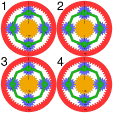
[12] In one arrangement, the planetary carrier (green in the diagram above) is held stationary, and the sun gear (yellow) is used as input.
Extending this case from the one above: So, with the planetary carrier locked, one turn of the sun gear results in
This type of gearing is sometimes used in tractors and construction equipment to provide high torque to the drive wheels.
In bicycle hub gears, the sun is usually stationary, being keyed to the axle or even machined directly onto it.
The fundamental formula of the planetary gear train with a rotating carrier is obtained by recognizing that this formula remains true if the angular velocities of the sun, planet and ring gears are computed relative to the carrier angular velocity.
This may be necessary to achieve smaller step changes in gear ratio when the overall package size is limited.
Compound planets have "timing marks" (or "relative gear mesh phase" in technical term).
In 2015, a traction based variant of the "stepped-planet" design was developed at the Delft University of Technology,[14] which relies on compression of the stepped planet elements to achieve torque transmission.
The use of traction elements eliminates the need to "timing marks" as well as the restrictive assembly conditions as typically found.
Compound planetary gears can easily achieve larger transmission ratio with equal or smaller volume.
At low input speed, because of the load on the output, the sun will be stationary and the planet carrier will rotate in the direction of the ring gear.
If the input speed is increased to overcome the load the converter turbine will turn the output shaft.
Because the torque converter itself is a load on the planet carrier, a force will be exerted on the sun gear.
Both the planet carrier and the sun gear extract energy from the system and apply it to the output shaft.
They provide a reduction in volume, multiple kinematic combinations, purely torsional reactions, and coaxial shafting.
Disadvantages include high bearing loads, constant lubrication requirements, inaccessibility, and design complexity.
The load in a planetary gear train is shared among multiple planets; therefore, torque capability is greatly increased.
The planetary gear train also provides stability due to an even distribution of mass and increased rotational stiffness.
In this case, all the loading is concentrated on a few contacting surfaces, making the gears wear quickly and sometimes crack.
But the planetary speed reducer has multiple gear contacting surfaces with a larger area that can distribute the loading evenly around the central axis.
Planetary gears have become popular in the maker community, due to their inherent high torque capabilities and compactness/efficiency[18].
Especially within 3D printing, they can be used to rapidly prototype a gear box, to then be manufactured with machining technologies later.
While down-gearing improves precision in unidirectional motion, it adds backlash to the system and so reduces its absolute positioning accuracy.

