Saturn V instrument unit
[1] NASA's contractor to manufacture the Saturn V Instrument Unit was International Business Machines (IBM).
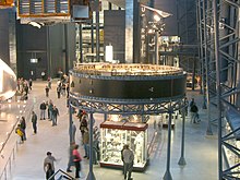
It was contained in an instrument unit like this one, a ring located between the rocket's third stage and the command and lunar modules.
The ring contained the basic guidance system components—a stable platform, accelerometers, a digital computer, and control electronics—as well as radar, telemetry, and other units.
The Bendix Corporation produced the platform, while IBM designed and built the unit's digital computer.
Guidance and control equipment was carried in canisters on top of the S-I first stage, and included the ST-90 stabilized platform, made by Ford Instrument Company and used in the Jupiter missile.
To more smoothly control engine ignition, thrust buildup and liftoff of the vehicle, restraining arms provided support and hold down at four points around the base of the S-IC stage.
Guidance during the second and third stage burns depended both on time and navigation measurements, in order to achieve the target orbit using the minimum fuel.
During the hour and a half after launch, tracking stations around the world had refined estimates of the vehicle's position and velocity, collectively known as its state vector.
The latest estimates were relayed to the guidance systems in the IU, and to the Command Module Computer in the spacecraft.
These impacts provided impulses that were recorded by the seismometer network to yield information about the geological structure of the Moon.
This type of construction was selected for its high strength to weight ratio, acoustical insulation, and thermal conductivity properties.
To facilitate handling the IU before it was assembled into the Saturn, the fore and aft protective rings, 6 inches tall and painted blue, were bolted to the top and bottom channels.
In the first and second stages (S-IC and S-II), the four outboard engines were gimbaled to control roll, pitch, and yaw.
Since the third (S-IVB) stage has only one engine, an auxiliary propulsion system was used for roll control during powered flight.
Each cold plate contains tapped bolt holes in a grid pattern which provides flexibility of component mounting.
Before flight, ground support equipment (GSE) supplies cooled, filtered ventilating air to the IU, entering via the large duct in the middle of the umbilical panel (location 7), and branching into two ducts at the top that are carried around the IU in the cable rack.
To reduce errors in sensing attitude and velocity, designers cut friction to a minimum in the platform gyros and accelerometers by floating the bearings on a thin film of dry nitrogen.
The nitrogen was supplied from a sphere holding 2 cu ft (56.6 L) of gas at 3,000 psig (pounds per square inch gauge, i.e. psi above one atmosphere) (20,7 MPa).
Gas from the supply sphere passes through a filter, a pressure regulator, and a heat exchanger before flowing through the bearings in the stable platform.
The control signal processor (location 15) provided power to and received inputs from the nine EDS rate gyros.
An electronic timer (location 17) was activated at liftoff and 30 seconds later energized relays in the EDS distributor which allowed multiple engine shutdown.
[clarification needed] Conditioned signals were routed to their assigned telemetry channel by the measuring distributor at location 10.
C-band radar transponders carried by the IU provided tracking data to the ground which were used to determine the vehicle's trajectory.
The transponder received coded or single pulse interrogation from ground stations and transmitted a single-pulse reply in the same frequency band (5.4 to 5.9 GHz).
The command communications system (CCS) provided for digital data transmission from ground stations to the LVDC.
Command data originated in the Mission Control Center, Houston, and was sent to remote stations for transmission to the launch vehicle.
The CCS system used five antennas: Power during flight originated with four silver-zinc batteries with a nominal voltage of 28±2 vdc.
Comparison of these photographs of the instrument unit shows that the configuration of components carried by this version changed, depending on the mission.
These images also show that some components (e.g., batteries, the ST-124 inertial platform) were installed in the IU after it had been stacked in the VAB on top of the S-IVB third stage.