Transformer
Perfect coupling implies infinitely high core magnetic permeability and winding inductance and zero net magnetomotive force (i.e. ipnp − isns = 0).
This introduces error but allows combination of primary and referred secondary resistances and reactance by simple summation as two series impedances.
[9] By operating at higher frequencies, transformers can be physically more compact because a given core is able to transfer more power without reaching saturation and fewer turns are needed to achieve the same impedance.
Consequently, the transformers used to step-down the high overhead line voltages were much larger and heavier for the same power rating than those required for the higher frequencies.
Transformers for higher frequency applications such as SMPS typically use core materials with much lower hysteresis and eddy-current losses than those for 50/60 Hz.
Large power transformers are vulnerable to insulation failure due to transient voltages with high-frequency components, such as caused in switching or by lightning.
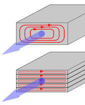
[27] The steel has a permeability many times that of free space and the core thus serves to greatly reduce the magnetizing current and confine the flux to a path which closely couples the windings.
One common design of laminated core is made from interleaved stacks of E-shaped steel sheets capped with I-shaped pieces, leading to its name of E-I transformer.
When power is then reapplied, the residual field will cause a high inrush current until the effect of the remaining magnetism is reduced, usually after a few cycles of the applied AC waveform.
[33] Distribution transformers can achieve low no-load losses by using cores made with low-loss high-permeability silicon steel or amorphous (non-crystalline) metal alloy.
For frequencies extending beyond the VHF band, cores made from non-conductive magnetic ceramic materials called ferrites are common.
Toroidal transformers are built around a ring-shaped core, which, depending on operating frequency, is made from a long strip of silicon steel or permalloy wound into a coil, powdered iron, or ferrite.
Other advantages compared to E-I types, include smaller size (about half), lower weight (about half), less mechanical hum (making them superior in audio amplifiers), lower exterior magnetic field (about one tenth), low off-load losses (making them more efficient in standby circuits), single-bolt mounting, and greater choice of shapes.
Because of the lack of a residual gap in the magnetic path, toroidal transformers also tend to exhibit higher inrush current, compared to laminated E-I types.
Ferrite toroidal cores are used at higher frequencies, typically between a few tens of kilohertz to hundreds of megahertz, to reduce losses, physical size, and weight of inductive components.
Small distribution transformers may achieve some of the benefits of a toroidal core by splitting it and forcing it open, then inserting a bobbin containing primary and secondary windings.
[38] High-frequency transformers operating in the tens to hundreds of kilohertz often have windings made of braided Litz wire to minimize the skin-effect and proximity effect losses.
It is a rule of thumb that the life expectancy of electrical insulation is halved for about every 7 °C to 10 °C increase in operating temperature (an instance of the application of the Arrhenius equation).
[40] With a great body of empirical study as a guide, transformer oil testing including dissolved gas analysis provides valuable maintenance information.
Building regulations in many jurisdictions require indoor liquid-filled transformers to either use dielectric fluids that are less flammable than oil, or be installed in fire-resistant rooms.
Polychlorinated biphenyls (PCBs) have properties that once favored their use as a dielectric coolant, though concerns over their environmental persistence led to a widespread ban on their use.
[45] Today, non-toxic, stable silicone-based oils, or fluorinated hydrocarbons may be used where the expense of a fire-resistant liquid offsets additional building cost for a transformer vault.
A large bushing can be a complex structure since it must provide careful control of the electric field gradient without letting the transformer leak oil.
In 1876, Russian engineer Pavel Yablochkov invented a lighting system based on a set of induction coils where the primary windings were connected to a source of AC.
[60] In 1878, the Ganz factory, Budapest, Hungary, began producing equipment for electric lighting and, by 1883, had installed over fifty systems in Austria-Hungary.
[57][61] In 1882, Lucien Gaulard and John Dixon Gibbs first exhibited a device with an initially widely criticized laminated plate open iron core called a 'secondary generator' in London, then sold the idea to the Westinghouse company in the United States in 1886.
[64] In the autumn of 1884, Károly Zipernowsky, Ottó Bláthy and Miksa Déri (ZBD), three Hungarian engineers associated with the Ganz Works, had determined that open-core devices were impracticable, as they were incapable of reliably regulating voltage.
The Edison Electric Light Company held an option on the US rights for the ZBD transformers, requiring Westinghouse to pursue alternative designs on the same principles.
[79] Stanley's first patented design was for induction coils with single cores of soft iron and adjustable gaps to regulate the EMF present in the secondary winding (see image).
Pre-wound copper coils could then be slid into place, and straight iron plates laid in to create a closed magnetic circuit.
White : Air, liquid or other insulating medium
Green spiral : Grain oriented silicon steel
Black : Primary winding
Red : Secondary winding