Engineering fit
ISO is the internationally accepted standard for defining engineering fits, but ANSI is often still used in North America.
Within each category are several codes to define the size limits of the hole or shaft – the combination of which determines the type of fit.
[1] The International Organization for Standardization system splits the three main categories into several individual fits based on the allowable limits for hole and shaft size.
Each fit is allocated a code, made up of a number and a letter, which is used on engineering drawings in place of upper & lower size limits to reduce clutter in detailed areas.
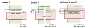
In a hole-basis system, the size of the hole remains constant and the diameter of the shaft is varied to determine the fit; conversely, in a shaft-basis system the size of shaft remains constant and the hole diameter is varied to determine the fit.
These codes can be used by machinists or engineers to quickly identify the upper and lower size limits for either the hole or shaft.
After the parts are joined, the mating surfaces will feel pressure due to friction, and deformation of the completed assembly will be observed.
Sliding fits in larger sizes may seize with small temperature changes due to little allowance for thermal expansion or contraction.
Loose running fits may be exposed to effects of corrosion, contamination by dust, and thermal or mechanical deformations.