Sloped armour
This improvement in protection is simply equivalent to the increase of area density and thus mass, and can offer no weight benefit.
When it hits a plate under a steep angle, its path might be curved, causing it to move through more armour – or it might bounce off entirely.
Shaped charge warheads may fail to penetrate or even detonate when striking armour at a highly oblique angle.
However, these desired effects are critically dependent on the precise armour materials used in relation to the characteristics of the projectile hitting it: sloping might even lead to better penetration.
For practical reasons this mechanism is most often applied on the front of the vehicle, where there is sufficient room to slope and much of the armour is concentrated, on the assumption that unidirectional frontal attack is the most likely.
The second mechanism is that shots hitting sloped armour are more likely to be deflected, ricochet or shatter on impact.
Even though the increased protection to a point, provided by angling a certain armour plate with a given normal thickness causing an increased line-of-sight (LOS) thickness, is of no consideration in armour vehicle design, it is of great importance when determining the level of protection of a designed vehicle.
In the sixties however long-rod penetrators, such as armour-piercing fin-stabilized discarding sabot rounds, were introduced, projectiles that are both very elongated and very dense in mass.
Also the deformed penetrator tends to act as a projectile of a very large diameter and this stretches out the remaining armour, causing it to fail more easily.
If these latter effects occur strongly – for modern penetrators this is typically the case for a slope between 55° and 65° – better protection would be provided by vertically mounted armour of the same area density.
Therefore, a very simplified model can be created providing a general idea and understanding of the basic physical principles behind these aspects of sloped armour design.
In this limiting case, after the hit, the projectile continues to penetrate until it has stopped transferring its momentum to the target matter.
The situation of the penetrating metal jet caused by the explosion of the shaped charge of high-explosive anti-tank (HEAT) ammunition, forms a good approximation of this ideal.
Therefore, if the angle is not too extreme, and the projectile is very dense and fast, sloping has little effect and no relevant deflection occurs.
Typical World War II Armour-Piercing shells were bullet-shaped and had a much lower velocity than a shaped charge jet.
Under the assumption that only elastic deformation occurs and that a target is solid, while disregarding friction, it is easy to calculate the proportion of energy absorbed by a target if it is hit by a projectile, which, if also disregarding more complex deflection effects, after impact bounces off (elastic case) or slides along (idealised inelastic case) the armour plate.
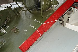
In this very simple model the portion of the energy projected to the target depends on the angle of slope: where However, in practice the AP-shells were powerful enough that the forces involved reach the plastic deformation limit and the elasticity of the plate could accumulate only a small part of the energy.
This implies that the formula above is principally valid also for the plastic deformation case, but because of the gauge grooved into the plate a larger surface angle
Thus the projectile has to work itself through more armour and, though in absolute terms thereby more energy could be absorbed by the target, it is more easily defeated, the process ideally ending in a complete ricochet.
One of the earliest documented instances of the concept of sloped armour is in the drawing of Leonardo da Vinci's fighting vehicle.
Sloped armour was actually used on nineteenth century early Confederate ironclads, such as CSS Virginia, and partially implemented on the first French tank, the Schneider CA1 in the First World War, but the first tanks to be completely fitted with sloped armour were the French SOMUA S35 and other contemporary French tanks like the Renault R35, which had fully cast hulls and turrets.
Sloped armour became very much the fashion after World War II, its most pure expression being perhaps the British Chieftain.


