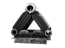
Three-drum boiler
Even the first boilers packed a large heating area into a compact volume, their difficulty was in manufacturing and particularly for their maintenance on-board ship.
Again, the Admiralty boiler (which omitted downcomers) was the culmination of this approach, placing the superheater within the tube bank, so as to encourage the necessary temperature difference.
The Admiralty boiler is usually considered to be a direct evolution of the Yarrow, although the White-Forster also had an influence, probably as a result of the large number in service with the Royal Navy.
[4] Downcomers were used, either the usual two large pipes, or an unusual but characteristic arrangement of four small 4-inch (10 cm) tubes to each drum.
[6] Initial design of the Normand boiler was as a development of the Du Temple, with the sharp corners of the tubes replaced by a smooth radiused bend, but still retaining the S shape.
The exhaust gas emerged into the heart-shaped space below the upper central drum, exiting to the funnel through the rear wall.
The number of their tubes was increased, such that they became the majority of the heating surface and the main gas path for the exhaust gases.
The wing drums became large enough to permit a man access inside, for cleaning and expanding new tubes into place.
When heat was also applied to the unheated arm, conventional theory predicted that the circulatory flow would slow or stop completely.
Flow was entirely within the heated watertubes, upwards within those closest to the furnace and downwards through those in the outer rows of the bank.
The first Yarrow water drums or "troughs" were D-shaped with a flat tubeplate, so as to provide an easy perpendicular mounting for the tubes.
This flexing led to leakage where the water tubes entered the drum; a problem, termed 'wrapperitis', which was shared with the White-Forster.
The circulation in a Yarrow boiler depended on a temperature difference between the inner and outer tube rows of a bank, and particularly upon the rates of boiling.
Whilst this is easy to maintain at low powers, a higher pressure Yarrow boiler will tend to have less temperature difference and thus will have less effective circulation.
[19] When superheating was adopted, primarily for use with steam turbines after 1900, the first Yarrow boilers placed their superheater coil outside the main tube bank.
[27] They ran at the unusually high pressure of 550 psi (3.8 MPa) and each axle was driven by a separate steam motor, designed by Abner Doble.
The first was supplied to Belgian Railways, the following three were built for the Société National des Chemins de Fer en Colombe of Colombia, but first shipped to Belgium for testing.
[2][28] Much of the design work was conducted at Admiralty Fuel Experimental Station[i] at Haslar and the first boilers were installed in three of the A class destroyers of 1927.
The advantage of placing the superheaters here was that they increased the temperature differential between the inner and outer tubes of the bank, thus encouraging circulation.
A circulation augmenter, a steel trough, was placed over the tops of the furnace-side tubes, encouraging a single central upwelling flow to above the water level, encouraging steam bubbles to escape and acting as a steam separator before the water re-circulated down the outer-side tubes.
The cold feedwater was thus heated to the same temperature as the boiler water before mixing with it, avoiding disturbance to the circulation path.
[29] Development work by Babcock & Wilcox resolved this by increasing the steam flow speed through the superheater to 150 ft/s (45.72 m/s), avoiding the problems of tube distortion and metallurgical failure.
[29] New boilers for the Nelson-class battleships and the Kent-class cruisers could achieve a superheat of 200–250 °F (93–121 °C) throughout the operating power range at 250 psi (1.7 MPa).
Unlike other water-wall designs, this additional water drum spanned only the centre of the furnace, the vertical tubes were enclosed in a refractory casing and did not form a closely packed solid wall.
[29] The concern was that a full water-wall would unbalance the existing header arrangement of the three-drum boiler, which indeed showed to be the case.
[29] The only large three-drum boiler used in a railway locomotive was Nigel Gresley's experimental Engine 10000 of 1924 for the LNER company.
[31] Having observed the benefits of higher pressures and compound engines in marine practice, Gresley was keen to experiment with this approach in a railway locomotive.
The rearward "firebox" area was wide and spanned the frames, placing the water drums at the limits of the loading gauge.
The first section, which included some water-tubes to the rear wall, was radiant heated and effectively a water-wall furnace, without any gas flow through the tube bank.
The second section had its gasflow arranged by steel and firebrick baffles so that the combustion gases entered through the centre and passed through the tube banks into the side flues, giving better convective heat transfer.