Compound steam engine
Multiple-expansion engines employ additional cylinders, of progressively lower pressure, to extract further energy from the steam.
There are many compound systems and configurations, but there are two basic types, according to how HP and LP piston strokes are phased and hence whether the HP exhaust is able to pass directly from HP to LP (Woolf compounds) or whether pressure fluctuation necessitates an intermediate "buffer" space in the form of a steam chest or pipe known as a receiver (receiver compounds).
Ideally, the steam would expand adiabatically, and the temperature would drop corresponding to the volume increase.
Only the smaller HP cylinder needs to be built to withstand the highest pressure, which reduces the overall weight.
[6] The first successful attempt to fly a heavier-than-air fixed-wing aircraft solely on steam power occurred in 1933, when George and William Besler converted a Travel Air 2000 biplane to fly on a 150 hp angle-compound V-twin steam engine of their own design instead of the usual Curtiss OX-5 inline or radial aviation gasoline engine it would have normally used.
[7][8] It is a logical extension of the compound engine (described above) to split the expansion into yet more stages to increase efficiency.
These engines use a series of double-acting cylinders of progressively increasing diameter and/or stroke and hence volume.
These cylinders are designed to divide the work into three or four equal portions, one for each expansion stage.
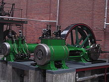
This engine was a cross-compound design to 2,500 ihp, driving a 24 ft, 90 ton flywheel, and operated until 1965.
[23] In the marine environment, the general requirement was for autonomy and increased operating range, as ships had to carry their coal supplies.
The old salt-water boiler was thus no longer adequate and had to be replaced by a closed fresh-water circuit with condenser.
These engines used a series of double-acting cylinders of progressively increasing diameter and/or stroke (and hence volume) designed to divide the work into three or four, as appropriate, equal portions for each expansion stage.
Where space is at a premium, two smaller cylinders of a large sum volume might be used for the low-pressure stage.
This allowed the crankshaft to be better balanced, resulting in a smoother, faster-responding engine which ran with less vibration.
This made the 4-cylinder triple-expansion engine popular with large passenger liners (such as the Olympic class), but was ultimately replaced by the virtually vibration-free steam turbine.
The development of this type of engine was important for its use in steamships as by exhausting to a condenser the water could be reclaimed to feed the boiler, which was unable to use seawater.
Prior to and during World War II, the expansion engine dominated marine applications where high vessel speed was not essential.
It was superseded by the steam turbine when speed was required, such as for warships and ocean liners.
HMS Dreadnought of 1905 was the first major warship to replace the proven technology of the reciprocating engine with the then-novel steam turbine.
For railway locomotive applications the main benefit sought from compounding was economy in fuel and water consumption plus high power/weight ratio due to temperature and pressure drop taking place over a longer cycle, this resulting in increased efficiency; additional perceived advantages included more even torque.
While designs for compound locomotives may date as far back as James Samuel's 1856 patent for a "continuous expansion locomotive",[24] the practical history of railway compounding begins with Anatole Mallet's designs in the 1870s.
Mallet locomotives were operated in the United States up to the end of mainline steam by the Norfolk and Western Railway.
The designs of Alfred George de Glehn in France also saw significant use, especially in the rebuilds of André Chapelon.
A wide variety of compound designs were tried around 1900, but most were short-lived in popularity, due to their complexity and maintenance liability.
It was realised by engineers that locomotives at steady speed were worked most efficiently with a wide-open regulator and early cut-off, the latter being set via the reversing gear.
Superheating eliminates the condensation and rapid loss of pressure that would otherwise occur with such expansion.
Large American locomotives used two cross-compound steam-driven air compressors, e.g. the Westinghouse 8 1/2" 150-D,[25] for the train brakes.
The presentation follows Sommerfeld's textbook, which contains a diagram (Figure 17) that is not reproduced for copyright reasons.
As each cylinder moves up and down, it exerts a vertical force on its mounting frame equaling
In one case (the first type of Vauclain compound), the pistons worked in the same phase driving a common crosshead and crank, again set at 90° as for a two-cylinder engine.

High-pressure steam (red) passes through three stages, exhausting as low-pressure steam (blue) to the condenser

High-pressure steam (red) passes through three stages, exhausting as low-pressure steam (blue) to the condenser


