Turbine blade
Fatigue is caused by the stress induced by vibration and resonance within the operating range of machinery.
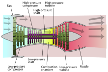
The turbine is connected to a compressor using a shaft (the complete rotating assembly sometimes called a "spool").
The temperature is then increased by combustion of fuel inside the combustor which is located between the compressor and the turbine.
[16] Turbine blades are subjected to stress from centrifugal force (turbine stages can rotate at tens of thousands of revolutions per minute (RPM)) and fluid forces that can cause fracture, yielding, or creep[nb 1] failures.
The development of superalloys in the 1940s and new processing methods such as vacuum induction melting in the 1950s greatly increased the temperature capability of turbine blades.
[16][20] Aside from alloy improvements, a major breakthrough was the development of directional solidification (DS) and single crystal (SC) production methods.
[18][21][22] Another major improvement to turbine blade material technology was the development of thermal barrier coatings (TBC).
[25] The main advantage of CMCs over conventional superalloys is their light weight and high temperature capability.
[26] GE Aviation successfully demonstrated the use of such SiC/SiC composite blades for the low-pressure turbine of its F414 jet engine.
Quantity of air required for this purpose is 1–3% of main flow and blade temperature can be reduced by 200–300 °C.
While all methods have their differences, they all work by using cooler air taken from the compressor to remove heat from the turbine blades.
A large internal surface area is desirable for this method, so the cooling paths tend to be serpentine and full of small fins.
In case of gas turbine the fluid outside is relatively hot which passes through the cooling passage and mixes with the main stream at the blade tip.
In case of turbine blades, the leading edge has maximum temperature and thus heat load.
[43] This technique consists of pumping the cooling air out of the blade through multiple small holes or slots in the structure.
A thin layer (the film) of cooling air is then created on the external surface of the blade, reducing the heat transfer from main flow, whose temperature (1300–1800 kelvins) can exceed the melting point of the blade material (1300–1400 kelvins).
The cooling effectiveness is mainly affected by the coolant flow parameters and the injection geometry.
[18] Injecting the cooler bleed into the flow reduces turbine isentropic efficiency; the compression of the cooling air (which does not contribute power to the engine) incurs an energetic penalty; and the cooling circuit adds considerable complexity to the engine.
The film cooling of turbine blades by using a dielectric barrier discharge plasma actuator was first proposed by Roy and Wang.
[48] A horseshoe-shaped plasma actuator, which is set in the vicinity of holes for gas flow, has been shown to improve the film cooling effectiveness significantly.
Following the previous research, recent reports using both experimental and numerical methods demonstrated the effect of cooling enhancement by 15% using a plasma actuator.
Cooling air is forced through these porous holes which forms a film or cooler boundary layer.
[36] In the narrow trailing edge film cooling is used to enhance heat transfer from the blade.
Air flows through internal channels of the strut and then passes through the porous shell to cool the blade.