VHF omnidirectional range
VOR [2] and the first DME(1950)[3] system (referenced to 1950 since different from today's DME/N) to provide the slant range distance, were developed in the United States as part of a U.S. civil/military program for Aeronautical Navigation Aids in 1945.
The phase difference is indicative of the bearing from the (D)VOR station to the receiver relative to magnetic north.
The intersection of radials from two different VOR stations can be used to fix the position of the aircraft, as in earlier radio direction finding (RDF) systems.
VOR stations are short range navigation aids limited to the radio-line-of-sight (RLOS) between transmitter and receiver in an aircraft.
Depending on the site elevation of the VOR and altitude of the aircraft Designated Operational Coverages (DOC) of at max.
Some of the older range stations survived, with the four-course directional features removed, as non-directional low or medium frequency radiobeacons (NDBs).
A worldwide land-based network of "air highways", known in the US as Victor airways (below 18,000 ft or 5,500 m) and "jet routes" (at and above 18,000 feet), was set up linking VORs.
VOR signals provide considerably greater accuracy and reliability than NDBs due to a combination of factors.
This means that if, on a perfectly clear day, you cannot see the transmitter from the receiver antenna, or vice versa, the signal will be either imperceptible or unusable.
Although the modern solid state transmitting equipment requires much less maintenance than the older units, an extensive network of stations, needed to provide reasonable coverage along main air routes, is a significant cost in operating current airway systems.
On these VORs, the amplitude modulation is achieved by rotating a slightly directional antenna exactly in phase with the reference signal at 30 revolutions per second.
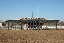
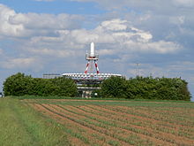
Modern installations are Doppler VORs (DVOR), which use a circular array of typically 48 omni-directional antennas and no moving parts.
The active antenna is moved around the circular array electronically to create a doppler effect, resulting in frequency modulation.
Decoding in the receiving aircraft happens in the same way for both types of VORs: the AM and FM 30 Hz components are detected and then compared to determine the phase angle between them.
This information is then fed over an analog or digital interface to one of four common types of indicators: In many cases, VOR stations have co-located distance measuring equipment (DME) or military Tactical Air Navigation (TACAN) – the latter includes both the DME distance feature and a separate TACAN azimuth feature that provides military pilots data similar to the civilian VOR.
While the operating principles are different, VORs share some characteristics with the localizer portion of ILS and the same antenna, receiving equipment and indicator is used in the cockpit for both.
Some VORs have a relatively small geographic area protected from interference by other stations on the same frequency—called "terminal" or T-VORs.
As RNAV systems have become more common, in particular those based on GPS, more and more airways have been defined by such points, removing the need for some of the expensive ground-based VORs.
[citation needed] There is some concern that GNSS navigation is subject to interference or sabotage, leading in many countries to the retention of VOR stations for use as a backup.
[clarification needed] The US FAA plans[21] by 2020 to decommission roughly half of the 967[22] VOR stations in the US, retaining a "Minimum Operational Network" to provide coverage to all aircraft more than 5,000 feet above the ground.
In the UK and the United States, DME transmitters are planned to be retained in the near future even after co-located VORs are decommissioned.
The VOR signal encodes a morse code identifier, optional voice, and a pair of navigation tones.
The navigation variable signal is encoded by mechanically or electrically rotating a directional, g(A,t), antenna to produce A3 modulation (grey-scale).
The pairing of transmitters offset equally high and low of the isotropic carrier frequency produce the upper and lower sidebands.
Closing and receding equally on opposite sides of the same circle around the isotropic transmitter produce F3 subcarrier modulation,
(24,000 g) makes mechanical revolution impractical, and halves (gravitational redshift) the frequency change ratio compared to transmitters in free-fall.
For example, in mountainous areas, the VOR may only provide sufficient signal strength and bearing accuracy along one runway approach path.
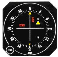
When the aircraft intercepts the 90° radial (due east of the VOR station) the needle will be centered and the To/From indicator will show "To".
In the illustration on the right, notice that the heading ring is set with 360° (north) at the primary index, the needle is centred and the To/From indicator is showing "TO".
Another method to intercept a VOR radial exists and more closely aligns itself with the operation of an HSI (Horizontal Situation Indicator).


red(F3-) green(F3) blue(F3+)
black(A3-) grey(A3) white(A3+)

red (F3-) green (F3) blue (F3+)
black (A3-) grey (A3) white (A3+)
USB transmitter offset is exaggerated
LSB transmitter is not shown