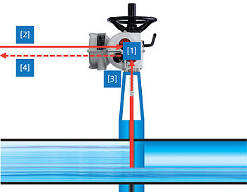
Valve actuator
A manual actuator employs levers, gears, or wheels to move the valve stem with a certain action.
As a safety feature, certain types of situations may require quicker operation than manual actuators can provide to close the valve.
Air pressure acts on a piston or bellows diaphragm creating linear force on a valve stem.
A pneumatic actuator may be arranged to be spring-closed or spring-opened, with air pressure overcoming the spring to provide movement.
A "double acting" actuator use air applied to different inlets to move the valve in the opening or closing direction.
Fluid pressure acting on a piston provides linear thrust for gate or globe valves.
Most types of hydraulic actuators can be supplied with fail-safe features to close or open a valve under emergency circumstances.
A diaphragm actuator is useful if the supply pressure is moderate and the valve travel and thrust required are low.
If there is a spring inside of the actuator, it will force the valve open or closed and will keep it in that position while power is restored.
This enables a high reduction ratio within the gear stage, leading to a low efficiency which is desired for the actuators.
Second: The output drive type used to transmit the torque or the thrust from the actuator to the valve shaft.
Mechanical torque-limiting devices are commonly used to prevent torque overload during manual operation.
Modern actuators include integral controls which process signals locally without any delay.
Another task of the actuator controls is to provide the DCS with feedback signals, e.g. when reaching a valve end position.
After receiving an operation command, the actuator moves the valve in direction OPEN or CLOSE.
The controls are programmed as to ensure that the actuator is switched off when exceeding the set torque limit.
Due to increasing decentralisation in automation technology and the introduction of micro processors, more and more functions have been transferred from the DCS to the field devices.
Modern positioners are equipped with self-adaptation i.e. the positioning behaviour is monitored and continuously optimised via controller parameters.
Study of the logged data allows the operation to be optimised by changing the parameters and the wear of both actuator and valve to be reduced.
The most distinctive feature of a closed-loop application is that changing conditions require frequent adjustment of the actuator, for example, to set a certain flow rate.
Actuator design must be able to withstand the high number of starts without any deterioration in control accuracy.
In addition to the static and dynamic load and response time required for the valve, the actuator must withstand the temperature range, corrosion environment and other conditions of a specific application.
Valve actuator applications are often safety related, therefore the plant operators put high demands on the reliability of the devices.
Failure of an actuator may cause accidents in process-controlled plants and toxic substances may leak into the environment.
Process-control plants are often operated for several decades which justifies the higher demands put on the lifetime of the devices.
The basic versions of most electric actuators are designed to the second highest enclosure protection IP 67.
When sizing the actuator, the ambient temperature and the selection of the correct lubricant are of major importance.
When a potentially explosive gas-air-mixture or gas-dust-mixture occurs, the actuator must not act as ignition source.
Actuators designed for these applications, being explosion-proof devices, have to be qualified by a test authority (notified body).
Small electric actuators can be used in a wide variety of assembly, packaging and testing applications.