Van der Pol oscillator
In the study of dynamical systems, the van der Pol oscillator (named for Dutch physicist Balthasar van der Pol) is a non-conservative, oscillating system with non-linear damping.
where x is the position coordinate—which is a function of the time t—and μ is a scalar parameter indicating the nonlinearity and the strength of the damping.
The Van der Pol oscillator was originally proposed by the Dutch electrical engineer and physicist Balthasar van der Pol while he was working at Philips.
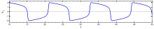
[2] Van der Pol found stable oscillations,[3] which he subsequently called relaxation-oscillations[4] and are now known as a type of limit cycle, in electrical circuits employing vacuum tubes.
When these circuits are driven near the limit cycle, they become entrained, i.e. the driving signal pulls the current along with it.
Van der Pol and his colleague, van der Mark, reported in the September 1927 issue of Nature that at certain drive frequencies an irregular noise was heard,[5] which was later found to be the result of deterministic chaos.
[6] The Van der Pol equation has a long history of being used in both the physical and biological sciences.
For instance, in biology, Fitzhugh[7] and Nagumo[8] extended the equation in a planar field as a model for action potentials of neurons.
, where the dot indicates the time derivative, the Van der Pol oscillator can be written in its two-dimensional form:[11] Another commonly used form based on the transformation
This is because the transition is not generic: when ε = 0, both the differential equation becomes linear, and the origin becomes a circular node.
[21] One can also write a time-independent Hamiltonian formalism for the Van der Pol oscillator by augmenting it to a four-dimensional autonomous dynamical system using an auxiliary second-order nonlinear differential equation as follows: Note that the dynamics of the original Van der Pol oscillator is not affected due to the one-way coupling between the time-evolutions of x and y variables.
This may, in principle, lead to quantization of the Van der Pol oscillator.
[24] Note the above Hamiltonian approach with an auxiliary second-order equation produces unbounded phase-space trajectories and hence cannot be used to quantize the van der Pol oscillator.
In the limit of weak nonlinearity (i.e. μ→0) the van der Pol oscillator reduces to the Stuart–Landau equation.
The Stuart–Landau equation in fact describes an entire class of limit-cycle oscillators in the weakly-nonlinear limit.
The quantum Stuart–Landau model has played an important role in the study of quantum synchronisation[25][26] (where it has often been called a van der Pol oscillator although it cannot be uniquely associated with the van der Pol oscillator).
[24] The forced, or driven, Van der Pol oscillator takes the 'original' function and adds a driving function Asin(ωt) to give a differential equation of the form: where A is the amplitude, or displacement, of the wave function and ω is its angular velocity.
Author James Gleick described a vacuum tube Van der Pol oscillator in his book from 1987 Chaos: Making a New Science.
[28] According to a New York Times article,[29] Gleick received a modern electronic Van der Pol oscillator from a reader in 1988.