Analog television
Camera systems used similar spinning discs and required intensely bright illumination of the subject for the light detector to work.
Analog television did not begin in earnest as an industry until the development of the cathode-ray tube (CRT), which uses a focused electron beam to trace lines across a phosphor coated surface.
The electron beam could be swept across the screen much faster than any mechanical disc system, allowing for more closely spaced scan lines and much higher image resolution.
The European and Australian PAL and the French and former Soviet Union SECAM standards were developed later and attempt to cure certain defects of the NTSC system.
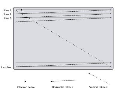
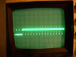
[5] A cathode-ray tube (CRT) television displays an image by scanning a beam of electrons across the screen in a pattern of horizontal lines known as a raster.
However, slow phosphor has the negative side-effect of causing image smearing and blurring when there is rapid on-screen motion occurring.
The maximum frame rate depends on the bandwidth of the electronics and the transmission system, and the number of horizontal scan lines in the image.
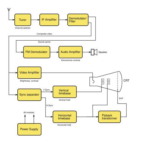
Signal reception is invariably done via a superheterodyne receiver: the first stage is a tuner which selects a television channel and frequency-shifts it to a fixed intermediate frequency (IF).
To ensure good linearity and thus fidelity, consistent with affordable manufacturing costs of transmitters and receivers, the video carrier is never modulated to the extent that it is shut off altogether.
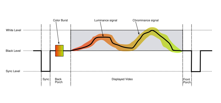
The same basic format (with minor differences mainly related to timing and the encoding of color) is used for PAL, NTSC, and SECAM television systems.
[7][8][9] The back porch is the portion of each scan line between the end (rising edge) of the horizontal sync pulse and the start of active video.
In some professional systems, particularly satellite links between locations, the digital audio is embedded within the line sync pulses of the video signal, to save the cost of renting a second channel.
However, the higher resolution portions of the Y signals do not cancel out, and so are equally present in R, G, and B, producing the higher-resolution image detail in monochrome, although it appears to the human eye as a full-color and full-resolution picture.
The subcarrier is within the bandwidth of the main luminance signal and consequently can cause undesirable artifacts on the picture, all the more noticeable in black and white receivers.
For this purpose, a short burst of the subcarrier, known as the colorburst, is transmitted during the back porch (re-trace blanking period) of each scan line.
The rest of the scan line follows, with the signal ranging from 0.3 V (black) to 1 V (white), until the next horizontal or vertical synchronization pulse.
These and the sync pulse itself are called the horizontal blanking (or retrace) interval and represent the time that the electron beam in the CRT is returning to the start of the next display line.
The sweep (or deflection) oscillators were designed to run without a signal from the television station (or VCR, computer, or other composite video source).
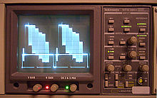
The lack of precision timing components in early equipment meant that the timebase circuits occasionally needed manual adjustment.
These and the sync pulse itself are called the horizontal blanking (or retrace) interval and represent the time that the electron beam in the CRT is returning to the start of the next display line.
The output waveforms from the timebase amplifiers are fed to the horizontal and vertical deflection coils wrapped around the CRT tube.
During the late 1960s in the UK, synchronous (with the scan line rate) power generation was introduced into solid state receiver designs.
The first country to make a wholesale switch to digital over-the-air (terrestrial television) broadcasting was Luxembourg in 2006, followed later in 2006 by the Netherlands.
[15] The Digital television transition in the United States for high-powered transmission was completed on 12 June 2009, the date that the Federal Communications Commission (FCC) set.
[19] Brazil switched to digital television on 2 December 2007 in São Paulo and planned to end analog broadcasting nationwide by 30 June 2016.
[21] The transition to TV 3.0 is expected to begin in 2025, with initial deployments planned for key cities such as São Paulo, Rio de Janeiro, and Brasília.
[citation needed] Large portions of Malaysia are covered by television broadcasts from Singapore, Thailand, Brunei, and Indonesia (from Borneo and Batam).
Starting from 1 November 2019, all regions in Malaysia were no longer using the analog system after the states of Sabah and Sarawak finally turned it off on 31 October 2019.
[26] However, in February 2023, the NTC postponed the ASO/DTV transition to 2025 due to many provincial television stations not being ready to start their digital TV transmissions.
[27] During the transition, DVB-T2 receivers and monetary compensations for purchasing of terrestrial or satellite digital TV reception equipment were provided to disabled people, World War II veterans, certain categories of retirees and households with income per member below living wage.