Vibratory stress relief

Residual stresses can occur through a variety of mechanisms including inelastic (plastic) deformations, temperature gradients (during thermal cycle), or structural changes (phase transformation).

These stresses often lead to distortion or warping of the structure during machining, assembly, testing, transport, field-use or over time.

If the strain amplitudes were increased to a level sufficient to cause instability in the residual stresses, fatigue damage would occur.

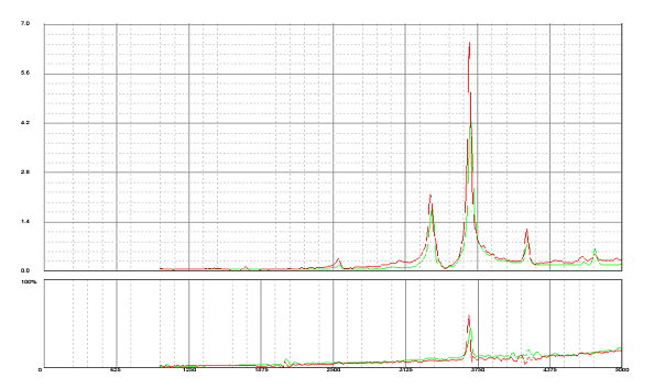
In the example below, which depicts a common resonance pattern change that occurs during vibratory stress relief, the large peak grew by 47%, while simultaneously shifting to the left 28-RPM, which is less than 0.75%.

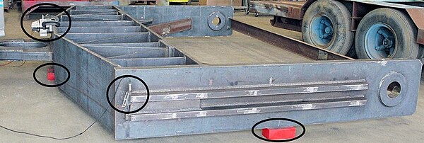
After stress relief treatment, the braces (rust-colored, structural beams), which are used to maintain the desired shape during welding, were removed.

VSR is not accepted by the Engineering community at large as a viable method of relaxing or reducing residual stresses in components that require it.

It has been known for many years, however, that TSR has limitations or shortcomings, specifically: Metal components, whose function would be enhanced by stress relief, and fall into one or more of the above categories, are strong candidates for VSR for quality-related reasons.

However, the lack of independent data to show that this technique is effective may mean that even that lesser investment is not of any value, so use of VSR should evaluated very carefully before proceeding.

Berry, Vibratory Stress Relief: Methods Used to Monitor and Document Effective Treatment, A Survey of Users, and Directions for Further Research, Proc.

Ring Time
Figure 1: A waveform that demonstrates ring time, which is the time period vibration continues, after resonant excitation ceases. [ 7 ]
Ring Time
Figure 2: Reverse ring time, or RRT, is the time period between the start of vibration excitation, and full resonant amplitude. [ 8 ]
Scan Rate Chart
Figure 3: The effects of scanning at different scan rates: 10 and 50-RPM/sec. Peaks that are scanned too quickly don't have enough time to reach full resonant amplitude, due to the RRT effect. The larger and heavier the structure, the greater the inertia, the longer the ring time (and reverse ring time): Thus, larger, heavier structures might require slower scan rates to plot accurate resonance patterns.
Ring Time
Figure 4: VSR Treatment Chart consists of two plots: The upper plot is workpiece acceleration, the lower plot is vibrator input power, simultaneously plotted vertically vs. a common horizontal axis of vibrator speed. Peaks in the acceleration data depict resonances; growth and shifting of the peaks are the response of the workpiece to treatment.
Ring Time
Figure 5: Vibratory Stress Relief was performed on this mild steel weldment weighing almost 12 tons. Overall size was 17' × 15' × 2' (≈ 5.2 × 5.6 × 0.6 meters). Workpiece was supported on three, red urethane load cushions (two of which are circled), which are positioned far from the corners of the workpiece to minimize damping, thus promoting resonance, which is required for stress relief to be achieved. The vibrator can be seen in the left, mid-ground (circled), and the accelerometer (vibration sensor whose output is proportional to acceleration), can be seen in the central, left, foreground (circled).