Voltage doubler
The capacitor is charged on the negative half cycles to the peak AC voltage (Vpk).
The peak-to-peak ripple is an enormous 2Vpk and cannot be smoothed unless the circuit is effectively turned into one of the more sophisticated forms.
[1] This is the circuit (with diode reversed) used to supply the negative high voltage for the magnetron in a microwave oven.
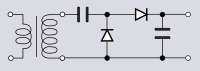
The Greinacher voltage doubler is a significant improvement over the Villard circuit for a small cost in additional components.
It is also called a Cockcroft–Walton multiplier after the particle accelerator machine built by John Cockcroft and Ernest Walton, who independently discovered the circuit in 1932.
[p 5][5] The concept in this topology can be extended to a voltage quadrupler circuit by using two Greinacher cells of opposite polarities driven from the same AC source.
[2] This form of circuit was, at one time, commonly found in cathode-ray-tube television sets where it was used to provide an extra high tension (EHT) supply.
Generating voltages in excess of 5 kV with a transformer has safety issues in terms of domestic equipment and in any case is uneconomical.
Each of the two peak detector cells operates on opposite half-cycles of the incoming waveform.
[8] More efficient circuits can be built by driving the switching devices from an external clock so that both functions, the chopping and multiplying, are achieved simultaneously.
This approach is especially useful in low-voltage battery-powered applications where integrated circuits require a voltage supply greater than the battery can deliver.
Frequently, a clock signal is readily available on board the integrated circuit and little or no additional circuitry is needed to generate it.
[9] Conceptually, perhaps the simplest switched capacitor configuration is that shown schematically in figure 5.
While CO is disconnected from the charge pump it partially discharges into the load resulting in ripple on the output voltage.
This ripple is smaller for higher clock frequencies since the discharge time is shorter, and is also easier to filter.
The practical maximum clock frequency in integrated circuits is typically in the hundreds of kilohertz.
The Dickson multiplier normally requires that alternate cells are driven from clock pulses of opposite phase.
[12] The Dickson multiplier is frequently employed in integrated circuits where the supply voltage (from a battery for instance) is lower than that required by the circuitry.
Figure 8 shows a Dickson voltage doubler using diode-wired n-channel enhancement type MOSFETs.
For a circuit using discrete components the Schottky diode would be a better choice of switching element for its extremely low voltage drop in the on state.
The circuit also has the advantage that the ripple frequency is doubled because there are effectively two voltage doublers both supplying the output from out of phase clocks.