Williamson amplifier
The original circuit, published in 1947 and addressed to the worldwide do it yourself community, set the standard of high fidelity sound reproduction and served as a benchmark or reference amplifier design throughout the 1950s.
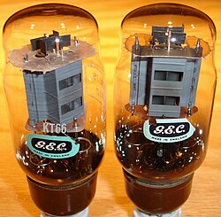
Deep feedback, triode-connected KT66 power tetrodes, conservative choice of standing currents, and the use of wide-bandwidth output transformer all contributed to the performance of the Williamson.
[4] The Williamson amplifier was sensitive to selection and matching of passive components and valves, and prone to unwanted oscillations at infrasonic and ultrasonic frequencies.
For this reason, and due to high costs of required quality components, manufacturers soon abandoned the Williamson circuit in favour of inherently more stable, cheaper and efficient three-stage, ultralinear or pentode-output designs.
[6] Early sound film and public address requirements were low, and customers were content[b] with crude but efficient and affordable transformer-coupled, class B amplifiers.
[6] By the middle of the 1930s Western Electric and RCA improved performance of their experimental audio equipment to a level approaching modern understanding of high fidelity, but none of these systems could be commercialized yet.
[7] Industry leaders of the 1930s agreed that the improvement of commercial amplifiers and loudspeakers would make sense only after the introduction of new physical media surpassing low-quality AM broadcasting and shellac records.
[9] British school of thought led by Walter Cocking[d] of Wireless World leaned to push-pull, class A, RC-coupled triode output stages.
[6] In 1943, in the middle of World War II, twenty-year-old Scotsman Theo Williamson failed mathematics exam and was discharged from the University of Edinburgh.
[20] On the contrary, wrote Williamson, slow but steady rise of distortion to 3–5%, as advocated by Kellogg, is distinctly unwanted in a high fidelity system.
[17] The prototypes impressed the Marconi management, who granted Williamson unlimited access to the company's test facilities and introduced him to the people from Decca Records.
[27][28] The latter provided Williamson with precious, exclusive test material - sample records of the experimental Decca ffrr system, the first true high fidelity medium in the United Kingdom.
[30][1] Chief editor H. F. Smith knew Williamson for his earlier contributions; he contacted the author directly and requested a detailed article written specifically for the DIY readers.
Cocking, as the technical editor of Wireless World, certainly had precedence; according to Peter Stinson, he was sceptical about the Williamson amplifier, believing that his own design needed no further improvements.
[39] In October 1949 – January 1950 and May 1952 Williamson published a series of articles on matching preamplifier stages and brief "Replies to Queries" concerning assembly and testing.
[l] Feedback attempts to overcome choking by increasing driver voltage swing, but fails because coupling capacitors cannot physically pass direct current.
[74] Later, technicians of the United States Naval Research Laboratory examined seven different commercially available Williamson amplifiers, and found that all of them oscillated at infrasonic frequencies of 2...3 Hz.
The extent of stability problem in the DIY community remains unknown: the editors of Wireless Worlds were flooded with readers' letters, but preferred to redirect them to Williamson.
[81] The transformer's nonlinearity also improved stability: at high signal currents effective inductance of the primary increased, causing a decrease in cutoff frequency and a rise in phase margin.
[85][86] DIYers had to tackle oscillations themselves: some added shunting capacitors to the screen grids, others tweaked layout and wiring, or deliberately narrowed the amplifier's bandwidth, negating the benefits of the original circuit.
Carbon and composition-type resistors generated excessive noise and caused harmonic distortion; American valves used as substitutes for the British types specified by Williamson, could not match their performance.
[90][89] Articles by professional engineers dealing with analysis and fine tuning of the Williamson amplifier were published relatively late, when the original DIY enthusiasm had already faded - in 1952,[91] 1957,[92] 1961.
[99] Contrary to recommendations by Cocking and Williamson, Keroes and his partner David Hafler used cathode shunt capacitors in most of their designs; by 1956 this approach became de facto industry standard.
[101] Later, fixed bias became a staple of Soviet and Russian Williamson-like designs that employed exotic output valves like the 6C4C directly-heated triode,[102] the GU-50 generator pentode[103][104] or the 6P45S horizontal deflection tetrode.
[109] In December 1951 Hafler and Keroes began promoting the ultralinear stage - a method of distributing load between anode and screen grid of a pentode or tetrode, invented by Alan Blumlein in the 1930s.
[115][31] Following the success of Hafler and Keroes, American manufacturers like Eico, The Fisher, Harman/Kardon and Marantz disposed with "obsolete" power triodes and switched to ultralinear designs.
[118] In September 1952 Williamson and Walker (then business partners in the development of the Quad Electrostatic Loudspeaker) agreed that the ultralinear stage was, indeed, preferable in mass production.
[122] North American consumer market was flooded with millions of similar, almost identical amplifiers and receivers claiming 25 to 20 W per channel, as well as clones of less powerful British designs like the Mullard 5-10.
The problem was partially addressed by the concept of subjective listening, advanced by Hafler and Keroes back in 1951: "Excellent measurements are a necessary but not a sufficient condition for the quality of sound.
[118] Objectively, many deep-feedback valve designs of the 1950s matched or exceeded the 0.1% distortion rating of the Williamson amplifier, but none could significantly improve on this figure.