YCbCr
Luma Y′ (with prime) is distinguished from luminance Y, meaning that light intensity is nonlinearly encoded based on gamma corrected RGB primaries.
Y′CbCr color spaces are defined by a mathematical coordinate transformation from an associated RGB primaries and white point.
Due to the number of existing TV sets and cameras, some form of backwards compatibility was desired for the new color broadcasts.
French engineer Georges Valensi developed and patented a system for transmitting RGB color as luma and chroma signals in 1938.
In the same way, a black and white broadcast could be received by a color television without any additional processing circuitry.
By doing this, subsequent image/video processing, transmission and storage can do operations and introduce errors in perceptually meaningful ways.
Y′CbCr is used to separate out a luma signal (Y′) that can be stored with high resolution or transmitted at high bandwidth, and two chroma components (CB and CR) that can be bandwidth-reduced, subsampled, compressed, or otherwise treated separately for improved system efficiency.
Typically the terms Y′CbCr, YCbCr, YPbPr and YUV are used interchangeably, leading to some confusion.
The equations below give a better picture of the common principles and general differences between these formats.
Y′CbCr signals (prior to scaling and offsets to place the signals into digital form) are called YPbPr, and are created from the corresponding gamma-adjusted RGB (red, green and blue) source using three defined constants KR, KG, and KB as follows: where KR, KG, and KB are ordinarily derived from the definition of the corresponding RGB space, and required to satisfy
When representing the signals in digital form, the results are scaled and rounded, and offsets are typically added.
The standard has 8-bit digitized versions of CB and CR scaled to a different range of 16 to 240.
The inverse transform is: The inverse transform without any roundings (using values coming directly from ITU-R BT.601 recommendation) is: This form of Y′CbCr is used primarily for older standard-definition television systems, as it uses an RGB model that fits the phosphor emission characteristics of older CRTs.
For ITU-R BT.709, the constants are: This form of Y′CbCr is based on an RGB model that more closely fits the phosphor emission characteristics of newer CRTs and other modern display equipment.
In different designs there are differences in the definitions of the R, G, and B chromaticity coordinates, the reference white point, the supported gamut range, the exact gamma pre-compensation functions for deriving R', G' and B' from R, G, and B, and in the scaling and offsets to be applied during conversion from R'G'B' to Y′CbCr.
In fact, when Y′CbCr is designed ideally, the values of KB and KR are derived from the precise specification of the RGB color primary signals, so that the luma (Y′) signal corresponds as closely as possible to a gamma-adjusted measurement of luminance (typically based on the CIE 1931 measurements of the response of the human visual system to color stimuli).
[6] The CL version, YcCbcCrc, codes:[5] The CL function can be used when preservation of luminance is of primary importance (see: Chroma subsampling § Gamma luminance error), or when "there is an expectation of improved coding efficiency for delivery."
[5] BT.2246 states that CL has improved compression efficiency and luminance preservation, but NCL will be more familiar to a staff that has previously handled color mixing and other production practices in HDTV YCbCr.
And back: The above conversion is identical to sYCC when the input is given as sRGB, except that IEC 61966-2-1:1999/Amd1:2003 only gives four decimal digits.
In this format, the "K" value is passed as-is, while CMY are used to derive YCbCr with the above matrix by assuming
Prior to the development of fast SIMD floating-point processors, most digital implementations of RGB → Y′UV used integer math, in particular fixed-point approximations.
Approximation means that the precision of the used numbers (input data, output data and constant values) is limited, and thus a precision loss of typically about the last binary digit is accepted by whoever makes use of that option in typically a trade-off to improved computation speeds.
Y′ values are conventionally shifted and scaled to the range [16, 235] (referred to as studio swing or "TV levels") rather than using the full range of [0, 255] (referred to as full swing or "PC levels").
This practice was standardized in SMPTE-125M in order to accommodate signal overshoots ("ringing") due to filtering.
As a result, only one 16-bit intermediate value is formed for each component, and a simple right-shift with rounding (x + 128) >> 8 can take care of the division.
[13] For studio-swing: For full-swing: Google's Skia used to use the above 8-bit full-range matrix, resulting in a slight greening effect on JPEG images encoded by Android devices, more noticeable on repeated saving.
Due to SIMD optimizations in libjpeg-turbo, the accurate version is actually faster.
4:4:4 is straightforward, as no pixel-grouping is done: the difference lies solely in how many bits each channel is given, and their arrangement.
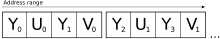
The basic YUV3 scheme uses 3 bytes per pixel, with the order y0, u0, v0, y1, u1, v1 (using "u" for Cb and "v" for Cr; the same applies to content below).
[17] In computers, it is more common to see a AYUV format, which adds an alpha channel and goes a0, y0, u0, v0, a1, y1, u1, v1, because groups of 32-bits are easier to deal with.