Three-phase electric power
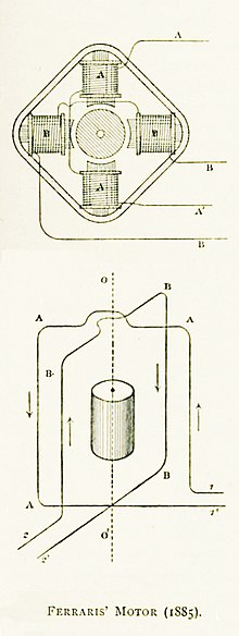
[6] Two months later Nikola Tesla gained U.S. patent 381,968 for a three-phase electric motor design, application filed October 12, 1887.
Figure 13 of this patent shows that Tesla envisaged his three-phase motor being powered from the generator via six wires.
Polyphase power enabled the use of water-power (via hydroelectric generating plants in large dams) in remote places, thereby allowing the mechanical energy of the falling water to be converted to electricity, which then could be fed to an electric motor at any location where mechanical work needed to be done.
[14] The possibility of transferring electrical power from a waterfall at a distance was explored at the Grängesberg mine.
A 45 m fall at Hällsjön, Smedjebackens kommun, where a small iron work had been located, was selected.
In 1893, a three-phase 9.5 kV system was used to transfer 400 horsepower (300 kW) a distance of 15 km (10 miles), becoming the first commercial application.
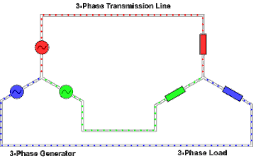
In a three-phase system feeding a balanced and linear load, the sum of the instantaneous currents of the three conductors is zero.
However, two-phase systems do not have neutral-current cancellation and thus use conductors less efficiently, and more than three phases complicates infrastructure unnecessarily.
Transformers may be wired to have a four-wire secondary and a three-wire primary, while allowing unbalanced loads and the associated secondary-side neutral currents.
The phases must be connected in the correct order to achieve the intended direction of rotation of three-phase motors.
A direct connection between two different phases is a short circuit and leads to flow of unbalanced current.
As compared to a single-phase AC power supply that uses two current-carrying conductors (phase and neutral), a three-phase supply with no neutral and the same phase-to-ground voltage and current capacity per phase can transmit three times as much power by using just 1.5 times as many wires (i.e., three instead of two).
Three-phase supplies have properties that make them desirable in electric power distribution systems: However, most loads are single-phase.
At the power station, transformers change the voltage from generators to a level suitable for transmission in order to minimize losses.
Most automotive alternators generate three-phase AC and rectify it to DC with a diode bridge.
The three-wire and four-wire designations do not count the ground wire present above many transmission lines, which is solely for fault protection and does not carry current under normal use.
Generally, there are four different types of three-phase transformer winding connections for transmission and distribution purposes: In North America, a high-leg delta supply is sometimes used where one winding of a delta-connected transformer feeding the load is center-tapped and that center tap is grounded and connected as a neutral as shown in the second diagram.
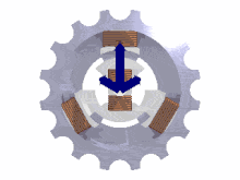
[21] The reason for providing the delta connected supply is usually to power large motors requiring a rotating field.
If the loads are evenly distributed on all three phases, the sum of the returning currents in the neutral wire is approximately zero.
A high-leg delta provides phase-to-neutral relationship of VLL = 2 VLN , however, LN load is imposed on one phase.
Line frequency flicker in light is detrimental to high-speed cameras used in sports event broadcasting for slow-motion replays.
Such rectifiers may be used for battery charging, electrolysis processes such as aluminium production and the electric arc furnace used in steelmaking, and for operation of DC motors.
Zigzag transformers may make the equivalent of six-phase full-wave rectification, twelve pulses per cycle, and this method is occasionally employed to reduce the cost of the filtering components, while improving the quality of the resulting DC.
In many European countries electric stoves are usually designed for a three-phase feed with permanent connection.
[35] Other usual three-phase loads in the domestic field are tankless water heating systems and storage heaters.
When properly designed, these rotary converters can allow satisfactory operation of a three-phase motor on a single-phase source.
This motor-generator combination can provide a frequency changer function as well as phase conversion, but requires two machines with all their expenses and losses.
The motor-generator method can also form an uninterruptible power supply when used in conjunction with a large flywheel and a battery-powered DC motor; such a combination will deliver nearly constant power compared to the temporary frequency drop experienced with a standby generator set gives until the standby generator kicks in.
A lamp or other indicator lights to show the sequence of voltages at the terminals for the given direction of shaft rotation.
[37] Conductors of a three-phase system are usually identified by a color code, to facilitate balanced loading and to assure the correct phase rotation for motors.


- V ab = (1∠α − 1∠α + 120°) √ 3 | V |∠α + 30°,
- V bc = √ 3 | V |∠α − 90°,
- V ca = √ 3 | V |∠α + 150°


- I a = I ab − I ca = √ 3 I ab ∠−30°,
- I b = I bc − I ab ,
- I c = I ca − I bc .
- S 3Φ = 3 V phase I * phase .