AC power
Hence, the instantaneous power, given by the product of voltage and current, is always positive, such that the direction of energy flow does not reverse and always is toward the resistor.
Insufficient reactive power can depress voltage levels on an electrical grid and, under certain operating conditions, collapse the network (a blackout).
[4] Engineers use the following terms to describe energy flow in a system (and assign each of them a different unit to differentiate between them): These are all denoted in the adjacent diagram (called a power triangle).
Reactive power does not do any work, so it is represented as the imaginary axis of the vector diagram.
It does, however, serve an important function in electrical grids and its lack has been cited as a significant factor in the Northeast blackout of 2003.
The mathematical relationship among them can be represented by vectors or expressed using complex numbers, S = P + j Q (where j is the imaginary unit).
For two systems transmitting the same amount of active power, the system with the lower power factor will have higher circulating currents due to energy that returns to the source from energy storage in the load.
Power factors are usually stated as "leading" or "lagging" to show the sign of the phase angle of current with respect to voltage.
Where the waveforms are purely sinusoidal, the power factor is the cosine of the phase angle (
Form the national grid the sub sectors are required to have minimum amount of power factor.
When there is inductance or capacitance in the circuit, the voltage and current waveforms do not line up perfectly.
These units can simplify to watts but are left as var to denote that they represent no actual work output.
Energy stored in capacitive or inductive elements of the network gives rise to reactive power flow.
Reactive power flow strongly influences the voltage levels across the network.
This allows all reactive power needed by the load to be supplied by the capacitor and not have to be transferred over the transmission lines.
Stored energy in the magnetic or electric field of a load device, such as a motor or capacitor, causes an offset between the current and the voltage waveforms.
The capacitor opposes this change, causing the current to lead the voltage in phase.
Induction machines are some of the most common types of loads in the electric power system today.
These machines use inductors, or large coils of wire to store energy in the form of a magnetic field.
This usually takes the form of capacitor banks being used to counteract the lagging power factor caused by induction motors.
Transmission connected generators are generally required to support reactive power flow.
Major delineations of the concept are attributed to Stanley's Phenomena of Retardation in the Induction Coil (1888) and Steinmetz's Theoretical Elements of Engineering (1915).
In 1920, a "Special Joint Committee of the AIEE and the National Electric Light Association" met to resolve the issue.
A new definition based on symmetrical components theory was proposed in 1993 by Alexander Emanuel for unbalanced linear load supplied with asymmetrical sinusoidal voltages: that is, the root of squared sums of line voltages multiplied by the root of squared sums of line currents.
In general, engineers are interested in the active power averaged over a period of time, whether it is a low frequency line cycle or a high frequency power converter switching period.
However, the time average of a function of the form cos(ωt + k) is zero provided that ω is nonzero.
Therefore, the only product terms that have a nonzero average are those where the frequency of voltage and current match.
In other words, it is possible to calculate active (average) power by simply treating each frequency separately and adding up the answers.
Furthermore, if voltage of the mains supply is assumed to be a single frequency (which it usually is), this shows that harmonic currents are a bad thing.
Typically this will consist of either just a capacitor (relying on parasitic resistance and inductance in the supply) or a capacitor-inductor network.

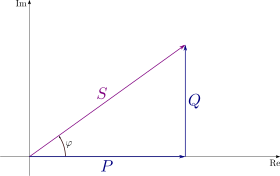
The complex power is the vector sum of active and reactive power. The apparent power is the magnitude of the complex power.
Active power , P
Reactive power , Q
Complex power , S
Apparent power , |S|
Phase of voltage relative to current ,

