Airfoil
Foils of similar function designed with water as the working fluid are called hydrofoils.
Airfoils can be designed for use at different speeds by modifying their geometry: those for subsonic flight generally have a rounded leading edge, while those designed for supersonic flight tend to be slimmer with a sharp leading edge.
[5] In some situations (e.g., inviscid potential flow) the lift force can be related directly to the average top/bottom velocity difference without computing the pressure by using the concept of circulation and the Kutta–Joukowski theorem.
[6] The wings and stabilizers of fixed-wing aircraft, as well as helicopter rotor blades, are built with airfoil-shaped cross sections.
Swimming and flying creatures and even many plants and sessile organisms employ airfoils/hydrofoils, common examples being bird wings, the bodies of fish, and the shape of sand dollars.
An airfoil-shaped wing can create downforce on an automobile or other motor vehicle, improving traction.
Airfoils are used in the design of aircraft, propellers, rotor blades, wind turbines and other applications of aeronautical engineering.
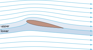
The curve represents an airfoil with a positive camber so some lift is produced at zero angle of attack.
The drop in lift can be explained by the action of the upper-surface boundary layer, which separates and greatly thickens over the upper surface at and past the stall angle.
In the region of the ailerons and near a wingtip a symmetric airfoil can be used to increase the range of angles of attack to avoid spin–stall.
Subsonic airfoils have a round leading edge, which is naturally insensitive to the angle of attack.
The cross section is not strictly circular, however: the radius of curvature is increased before the wing achieves maximum thickness to minimize the chance of boundary layer separation.
This elongates the wing and moves the point of maximum thickness back from the leading edge.
Supersonic airfoils are much more angular in shape and can have a very sharp leading edge, which is very sensitive to angle of attack.
A supercritical airfoil has its maximum thickness close to the leading edge to have a lot of length to slowly shock the supersonic flow back to subsonic speeds.
Analyzing the Navier–Stokes equations in the linear regime shows that a negative pressure gradient along the flow has the same effect as reducing the speed.
So with the maximum camber in the middle, maintaining a laminar flow over a larger percentage of the wing at a higher cruising speed is possible.
Under certain conditions, insect debris on the wing will cause the loss of small regions of laminar flow as well.
[7] Before NASA's research in the 1970s and 1980s the aircraft design community understood from application attempts in the WW II era that laminar flow wing designs were not practical using common manufacturing tolerances and surface imperfections.
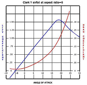
An example of a general purpose airfoil that finds wide application, and pre–dates the NACA system, is the Clark-Y.
Finally, important concepts used to describe the airfoil's behaviour when moving through a fluid are: In two-dimensional flow around a uniform wing of infinite span, the slope of the lift curve is determined primarily by the trailing edge angle.
It was devised by German mathematician Max Munk and further refined by British aerodynamicist Hermann Glauert and others[17] in the 1920s.
[20] In the mid-late 2000s, however, a theory predicting the onset of leading-edge stall was proposed by Wallace J. Morris II in his doctoral thesis.
[21] Morris's subsequent refinements contain the details on the current state of theoretical knowledge on the leading-edge stall phenomenon.
[25][26] The flow across the airfoil generates a circulation around the blade, which can be modeled as a vortex sheet of position-varying strength γ(x).
[27] If the main flow V has density ρ, then the Kutta–Joukowski theorem gives that the total lift force F is proportional to[28][29]
must balance an inverse flow from V. By the small-angle approximation, V is inclined at angle α-dy⁄dx relative to the blade at position x, and the normal component is correspondingly (α-dy⁄dx)V. Thus, γ(x) must satisfy the convolution equation
and then expanding both dy⁄dx and γ(x) as a nondimensionalized Fourier series in θ with a modified lead term:
The aerodynamic center is the position at which the pitching moment M′ does not vary with a change in lift coefficient:[28]
Thin-airfoil theory shows that, in two-dimensional inviscid flow, the aerodynamic center is at the quarter-chord position.