Antenna tuner
However, despite its name, an antenna 'tuner ' actually matches the transmitter only to the complex impedance reflected back to the input end of the feedline.
If both tuner and transmission line were lossless, tuning at the transmitter end would indeed produce a match at every point in the transmitter-feedline-antenna system.
[3][4] With lossy feedlines (such as commonly used 50 Ohm coaxial cable) maximum power transfer only occurs if matching is done at both ends of the line.
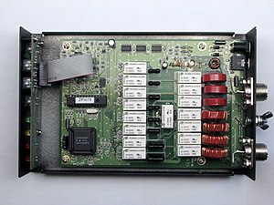
Solid-state power amplifiers operating from 1–30 MHz typically use one or more wideband transformers wound on ferrite cores.
This feedline system design has the advantage of reducing the retuning required when the operating frequency is changed.
There are several designs for impedance matching using an autotransformer, which is a single-wire transformer with different connection points or taps spaced along the windings.
When two differently-grounded cables or circuits must be connected but the grounds kept independent, a full, two-winding transformer with the desired ratio is used instead.
The three equal windings shown are wired for a common ground shared by two unbalanced lines (so this design is called an unun), and can be used as 1:1, 1:4, or 1:9 impedance match, depending on the tap chosen.
A single, typical, commercially available balun can cover frequencies from 3.5–30.0 MHz, or nearly the entire shortwave radio band.
Antenna coupling or feedline matching circuits are also narrowband for any single setting, but can be re-tuned more conveniently.
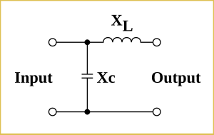
This is called an L network not because it contains an inductor, (in fact some L-networks consist of two capacitors), but because the two components are at right angles to each other, having the shape of a rotated and sometimes reversed English letter 'L'.
[10] So for example, the three circuits in the left column and the two in the bottom row have the series (horizontal) element on the out side are generally used for stepping up from a low-impedance input (transmitter) to a high-impedance output (antenna), similar to the example analyzed in the section above.
The top two circuits in the right column, with the series (horizontal) element on the in side, are generally useful for stepping down from a higher input to a lower output impedance.
In cases where the load is highly reactive – such as an antenna fed with a signals whose frequency is far away from any resonance – the opposite configuration may be required.
Here the inherent capacitance of a short, random wire antenna is so high that the L-network is best realized with two inductors, instead of aggravating the problem by using a capacitor.
The L-network using only capacitors will have the lowest loss, but this network only works where the load impedance is very inductive, making it a good choice for a small loop antenna.
If additional filtering is desired, the inductor can be deliberately set to larger values, thus providing a partial band pass effect.
When adjusted for minimum loss, the SPC tuner will have better harmonic rejection than the high-pass T due to its internal tank circuit.
When possible, an automatic or remotely-controlled tuner in a weather-proof case at or near the antenna is convenient and makes for an efficient system.
[18][19] When the ATU must be located near the radio for convenient adjustment, any significant SWR will increase the loss in the feedline.
For that reason, when using an ATU at the transmitter, low-loss, high-impedance feedline is a great advantage (open-wire line, for example).
However, if the feedline-antenna combination is 'lossy' then an identical high SWR may lose a considerable fraction of the transmitter's power output.
Without an ATU, the SWR from a mismatched antenna and feedline can present an improper load to the transmitter, causing distortion and loss of power or efficiency with heating and/or burning of the output stage components.
Tube transmitters and amplifiers usually have an adjustable output network that can feed mismatched loads up to perhaps 3:1 SWR without trouble.
Further, since tubes are electrically robust (even though mechanically fragile), tube-based circuits can tolerate very high backlash current without damage.
These patterns are often required by law to include nulls in directions that could produce interference as well as to increase the signal in the target area.
Adjustment of the ATUs in a multitower array is a complex and time consuming process requiring considerable expertise.
For International Shortwave (50 kW and above), frequent antenna tuning is done as part of frequency changes which may be required on a seasonal or even a daily basis.
Modern shortwave transmitters typically include built-in impedance-matching circuitry for SWR up to 2:1 , and can adjust their output impedance within 15 seconds.
Balanced transmission lines of 300 Ohms or more were more-or-less standard for all shortwave transmitters and antennas in the past, even by amateurs.