Attenuator (electronics)
An attenuator is a passive broadband electronic device that reduces the power of a signal without appreciably distorting its waveform.
An attenuator is effectively the opposite of an amplifier, though the two work by different methods.
An attenuator is often referred to as a "pad" in audio electronics.
[a] Attenuators are usually passive devices made from simple voltage divider networks.
For higher frequencies precisely matched low voltage standing wave ratio (VSWR) resistance networks are used.
Fixed attenuators in circuits are used to lower voltage, dissipate power, and to improve impedance matching.
In measuring signals, attenuator pads or adapters are used to lower the amplitude of the signal a known amount to enable measurements, or to protect the measuring device from signal levels that might damage it.
Attenuators are also used to 'match' impedance by lowering apparent SWR (Standing Wave Ratio).
For instance, attenuators used with coaxial lines would be the unbalanced form while attenuators for use with twisted pair are required to be the balanced form.
Four fundamental attenuator circuit diagrams are given in the figures on the left.
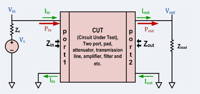
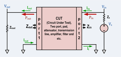
Since an attenuator circuit consists solely of passive resistor elements, it is both linear and reciprocal.
If the circuit is also made symmetrical (this is usually the case since it is usually required that the input and output impedance Z1 and Z2 are equal), then the input and output ports are not distinguished, but by convention the left and right sides of the circuits are referred to as input and output, respectively.
Various tables and calculators are available that provide a means of determining the appropriate resistor values for achieving particular loss values, such as that published by the NAB in 1960 for losses ranging from 1/2 to 40 dB, for use in 600 ohm circuits.
[1] Key specifications for attenuators are:[2] Radio frequency attenuators are typically coaxial in structure with precision connectors as ports and coaxial, micro strip or thin-film internal structure.
Above SHF special waveguide structure is required.
Important characteristics are: The size and shape of the attenuator depends on its ability to dissipate power.
RF attenuators are used as loads for and as known attenuation and protective dissipation of power in measuring RF signals.
[3] A line-level attenuator in the preamp or a power attenuator after the power amplifier uses electrical resistance to reduce the amplitude of the signal that reaches the speaker, reducing the volume of the output.
A line-level attenuator has lower power handling, such as a 1/2-watt potentiometer or voltage divider and controls preamp level signals, whereas a power attenuator has higher power handling capability, such as 10 watts or more, and is used between the power amplifier and the speaker.
This section concerns pi-pads, T-pads and L-pads made entirely from resistors and terminated on each port with a purely real resistance.
Each resistor in each type of pad discussed is given a unique designation to decrease confusion.
The L-pad component value calculation assumes that the design impedance for port 1 (on the left) is equal or higher than the design impedance for port 2.
Passive, resistive pads and attenuators are bidirectional two-ports, but in this section they will be treated as unidirectional.
The loss is a monotonic function of the impedance ratio.
The preceding equations are trivially invertible, but if the loss is not enough, some of the t-pad components will have negative resistances.
It is always possible to represent a resistive pi pad as a two-port.
The preceding equations are trivially invertible, but if the loss is not enough, some of the pi-pad components will have negative resistances.
Because the pad is entirely made from resistors, it must have a certain minimum loss to match source and load if they are not equal.
Although a passive matching two-port can have less loss, if it does it will not be convertible to a resistive attenuator pad.
Once these parameters have been determined, they can be implemented as a T or pi pad as discussed above.